jonescg
100 MW
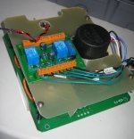
Full-Throttle kindly produced some Gerbers for me of the main control board. Too many high voltage wires hanging around inside this box, too much potential for a short somewhere. So I figure this board will simplify things greatly.


Now the whole lot goes together much more smoothly and clean. Just have to set the relay logic board up and it's done.
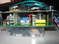
The resistors in the middle are the precharge. I was going to use four 2.2kR resistors in parallel, but I dropped the packet and the bastards broke in half! So now I have two 47kR and two 1kR resistors for about 490 ohms of precharge resistance. Gives a full precharge in 1 second. The high voltage precharge relay from Gigavac is soldered in nicely and no longer needs the jam nut. For voltage monitoring I'll be using the Cycle Analyst with a Vex connection from the voltage divider below. It offers a 1:140 division which should be about 5 V for full charge, and 3.9 V when flat.
Just need to devise some convenient plugs for the contactor LEDs and the 12 V supply.


