Kaabo Wolf Warrio 11+ 60v with TRONIC VESC performance package Battery shutoff while riding and will not charge or

Joined
May 11, 2021
Messages
15
I have a Kaabo Wolf Warrior 11+ 60v with the TRONIC 250 VESC performance package/upgrade kit, here's the problem.

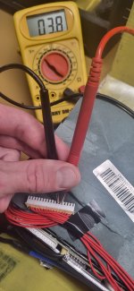
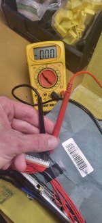
I took the scooter out for a ride, battery was at 93% (I left room for the regen braking) and about 1/4 from my house it shut off while I was riding it (~25mph, pretty slow). When I got home I found that the battery wouldn't charge and it wouldn't output any power but when I connected it to the power meter it still showed the battery had ~91% battery left (67.8v). If I plug the battery into the charger, it will not charge BUT if I connect the battery to the controllers, then connect both chargers to the battery and then connect the chargers to an outlet, the controllers will turn on (this is the only way that I know of to connect the VESC tool to the controllers when experiencing battery problems) and then when I check the VESC tool it will show the battery info. If I turn the throttle, the motors will go but you can tell the motors are being powered by the charges weak output of 68.8v @ 1.5a so it's not much.

I tried jump-starting/waking up the battery via the charger ports to no avail.

If anyone had to guess, would you have to agree that the BMS is possibly fried? Does anyone know if there's a fuse that might have blown inside the battery that could be replaced? Thank you for your help!
 
It could also be a cell (or group) that is either damaged or with damaged interconnects to other cells in the same group (reducing capacity/capability) or disconnected from it's balance wire to the BMS.

What are the voltages across each pair of balance wires measured *at the BMS connector's solder pads* on the BMS itself? (also including from the first (most negative) balance wire to the thick main negative wire from the cells, and from the last (most positive) balance wire to the thick main positive wire from the cells).

If all of these are exactly the same voltage, then all of the balance wires and cells are good. If any of them is different (especially radically different) it may indicate a cell problem. If any of them is zero, it may indicate a broken balance wire.
 
All the cells showed the exact same voltage.

No corrosion on the cell groups or any of the contact spots, no smell of burnt wires or anything.

Should I just bypass the BMS and just use the VESC BMS instead?
 
It could also be a cell (or group) that is either damaged or with damaged interconnects to other cells in the same group (reducing capacity/capability) or disconnected from it's balance wire to the BMS.

What are the voltages across each pair of balance wires measured *at the BMS connector's solder pads* on the BMS itself? (also including from the first (most negative) balance wire to the thick main negative wire from the cells, and from the last (most positive) balance wire to the thick main positive wire from the cells).

If all of these are exactly the same voltage, then all of the balance wires and cells are good. If any of them is different (especially radically different) it may indicate a cell problem. If any of them is zero, it may indicate a broken balance wire.
Battery: 60v 35Ah 18650 Lithium Ion battery pack from a Kaabo Wolf Warrior 11
How this happened: I used too high of regen settings.


When I measured voltages of each parallel group of cells at the BMS sense pins, the first 13 of the 16 show normal voltages but then the last 2nd to last 2 sense pins show 0.0v and the last pin shows 0.2v.


As I promised, I've attached pictures of what I was telling you:
 

Attachments

  • 20230507_151204.jpg
    20230507_151204.jpg
    875.5 KB · Views: 4
  • 20230507_151225.jpg
    20230507_151225.jpg
    866.3 KB · Views: 4
Hello,

You helped me in that thread and it's taken me many months to get back to it, but I have finally opened up the battery and had a look around.


Battery: 60v 35Ah 18650 Lithium Ion battery pack from a Kaabo Wolf Warrior 11

How this happened: I used too high of regen settings.

When I measured voltages of each parallel group of cells at the BMS sense pins, the first 13 of the 16 show normal voltages but then the last 3 show 0.0v.

Do you think those 3 groups of cells are bad or just maybe the wire fried?

If the cells show 0v at the BMS itself, the next step is to check those cells at the cells own +/-. If they are also 0v there, then the cells are actually dead and need to be replaced. ****

If they read normal, the exact same voltage as all the other cells, then there is a problem with the connection between the cells and the BMS. Fixing that would then let the BMS reactivate the output, as it would see a safe voltage there again, instead of the 0v that it's designed to protect against charge or discharge for, because that low a voltage on a cell for real causes internal damage that can lead to a fire if recharged/discharged.


**** If the cells are actually dead, 0v, then two main causes exist; the first sounds most likely in this case, but you should still test for the second after replacing the cells to prevent damage to the new ones:

--a cell could have failed internally and drained the others in parallel with it down to match it. This is fixed by replacing all the cells in the group, which you'd have to do in this event anyway. It might appear as a sudden failure if there was already a defect and something just triggered it / made it much worse. A high current might do this, either charge or discharge, especially if the cell was already full or near full and the charge durrent brought the voltage far enough up above normal full-cell voltage, or if it was already near empty and the discharge current brought the voltage far enough below normal empty-cell voltage.

--The BMS's balancer could have stuck on, and drained the group over time. It might appear as a sudden failure if the group drained to near empty over a few hours or days, and then the bike was ridden, rapidly draining it further until it drops below cell-level LVC of the BMS and it shuts off, and then the balancer finishes draining the cells to below empty.


Also...when measuring at the sense connector, are there the same number of wires as the number of series cell groups +1? If there are more wires than groups + 1, then some of those wire pairs are probably wired to the same point to make the BMS correctly read the cells (some BMS can be used with multiple pack types, just wiring this connector differently for each one).

In this event, you'll need to trace the wires from the connector to the connection points on the cell groups, and draw out what you measure. Then you can see which wires are electrically the same point, and are supposed to read 0V across them, and which are cell groups that read 0V, which isn't supposed to happen.
 
The 60 volt battery pack has two cell groups (pins 14 & 15 on bms pins) that show 0.0volts, and the last group 16 shows 0.12v.

Is it possible to remove groups 14 & 15? Would I need to cut them out of the pack or could I use a smart BMS (Like ANT) to disable the cell groups and let the battery run as a 14s instead of a 16s?
<snip>

And for group 16, I'm just going to try to balance charge it.
I would not recharge it, it is so low a voltage it is unsafe to recharge, and has the potential to be a fire hazard. Even if it doesn't start a fire later on, it will never behave as it should, or have the capacity even the others still do.

In that event, you have a 13s pack, which is a "48v" battery. At a guess, the controller's LVC is probably around that voltage, so you could still use the pack to run the system but not for very long--once the pack reaches it's nominal voltage or a bit more, under load, the controller will start cutting out, and then just shutdown until you recharge.

The same thing will happen (after a little longer amount of time) even if you recharge the 16th group and keep the pack as 14s.

If the controller's LVC is higher, it'll cut out sooner, if it's lower, then later.


To use the pack in any of these configurations, you'd have to remove the groups. If the BMS you have will operate normally with the last three (most positive) balance wires disconnected, then you can just keep using that one pretty simply this way, assuming you can trust this BMS not to kill the rest of your cells (if it is the cause of draining the others).

Some BMS require different wiring, skipping some unused groups and using wires before and after those, but these are BMS-model-specific so you would have to find out the model of BMS and then either find an ad for it that shows you this configuration (or one of the threads here on ES that happens to show this for it), or contact the manufacturer to find out. Or experiment, but this can result in damage to the BMS balance / sense wires that you won't know about until it causes another problme with the pack.

If not, you'd have to get a different BMS for the new series configuration.

If I could get that last cell group up to nominal voltage (even though the Ah will be reduced) then I could remove cell groups 14 & 15, making the 16s a 14s. Then if all works, I would just wire this battery pack in parallel with 2 other 52v packs I have.

All right well that makes sense thank you! I went ahead and bought a ANT Smart BMS 8s to 20s,.
 
Back
Top