Back to the drawing board on this build. New parameters as follow:
- - No freewheeling cranks: freewheeling will happen on a shared motor/crank jackshaft
- 3 speed rear cassette using a front derailleur shifter and custom spaced rear cassette: The rear cassette will also function as an effective 2nd stage reduction, reducing some of the losses inherent in all freewheeling crank designs (they just get transferred over to the human side)
- Print as much of this thing as possible out of ABS: If it breaks, I'll redesign it and if it breaks again then I'll make it out of metal
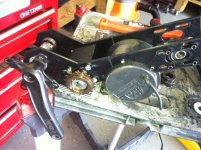
I don't really know if this will work, but I'll give it a shot. I ran out of welding gas and decided now is as good a time as any to try a printed mid drive. Printing the drive also reduces the amount of time required in the garage, which is precious these days. I'll still be using the heavy, pig-of-a-motor BLT-500 and I'm stealing a bunch of the GNG mount ideas as well. So, here goes...
My idea is to maximize the efficiency of the motor to the rear gears and use human input as the secondary input. This means I'll be stepping up the crank driven RPM's through a 2 stage (what's the opposite of reduction??) chain drive that will meet the motor at a common jackshaft placed just in front of the crank. The chain will go around the crank then directly to the rear cluster- I stole this idea from crossbreak (http://endless-sphere.com/forums/download/file.php?id=101131).
This is the first design I'm trying out:

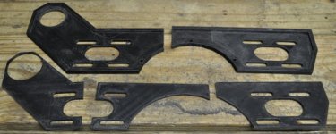
Because the build volume on my printer is only about 195x195mm, I split the plate in two to print:

I printed this first mock-up plate (2 sides) using only 5% infill- this means that inside the plate, it is 95% air. This also decreases the amount of time to print and plastic filament required by a factor of 3 (according to pronterface, the program that runs my printer).

This is a very flimsy print in the lateral direction, but even at this low infill, it is very stiff in the vertical direction. At this point, I'm thinking the final design will incorporate a second layer which I'll bond on to the first (both 4mm thick, total of 8mm ABS in all the places that count). I'll incorporate some triangulation into the second layer to further increase strength. If that doesn't work, then at least I've got a nice pattern to cut my new side plates out of cromo. It's just so much easier to dink around in sketchup and then print parts though :lol: .
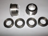
The next main element is the blocks that hold the bearings.
View attachment 6
I printed these at 10% infill, but they still took 3 1/2 hours just for this one. Another problem I'll be running into is common when printing bulky structures in ABS and that is edge-curling. Here you can see the worst of it.

As the layers of plastic cool and contract the act to pull the corners up. The middle is still dead, glass flat and that's all that matters on this build- the top is also flat, so I theorize that the curled edges warp the sides a bit. This edge curling will only get worse as i increase the plastic infill percentage. I think I'll incorporate a steel tube to hold the bearing inside this hunk of plastic- this should decrease the required amount of plastic, fingers crossed.
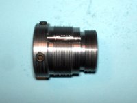
A couple more shots of the bearing block:


I'll be able to get a little time in on this over the weekend to at least get it mocked up to check clearances on all the sprockets/cranks etc. I'm not sure how wide of a bottom bracket I'll need just yet.


![Adj MM parts[1].JPG Adj MM parts[1].JPG](https://endless-sphere.com/sphere/data/attachments/68/68601-312c271c294527b7b17217bcd4d9fc07.jpg)
![Adj mount 2[1].JPG Adj mount 2[1].JPG](https://endless-sphere.com/sphere/data/attachments/68/68602-4547c6c439849185939ad715ab3576d8.jpg)
![Adj mount 3[1].JPG Adj mount 3[1].JPG](https://endless-sphere.com/sphere/data/attachments/68/68603-29634a6afca8de5874d028d35b7af3ad.jpg)
![Batt Mount 1[1].JPG Batt Mount 1[1].JPG](https://endless-sphere.com/sphere/data/attachments/68/68604-e1c899dd974e62a695f9442d7bcbc720.jpg)
![Batt Mount 2[1].JPG Batt Mount 2[1].JPG](https://endless-sphere.com/sphere/data/attachments/68/68605-57d80046eeb2d8ef279cd71d9989db41.jpg)
![Batt Mount 3[1].JPG Batt Mount 3[1].JPG](https://endless-sphere.com/sphere/data/attachments/68/68606-b0c4cec5b55cb6789f7000333364ca18.jpg)