Kona Stinky GM BLT-500 mid drive- frame mounted batteries

Very cool! You should consider a change to the crossbreak style where the drive goes directly to the rear cluster rather than going down in ratio only to go back up again. I think there is a good bit of efficiency there and you can do away with the pricey ENO on the cranks! Could be less noisy as well!

How is the motor taking the 3k watts lately? I am liking it for size and ease of construction!
 
Has anyone had this motor apart? I wonder if there is any weight that can be taken off??
 
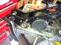
D@mn, are you spying on me Whip? Do you have a camera in my garage!?! :lol: I've ordered some #25 sprockets/chain with the intention of expanding on my previous attempts (pics in some of the first posts of this thread) at driving the rear cluster directly from the jack shaft. I like where crossbreak's chainline goes and will copy this positioning- jack shaft close to the bottom bracket with the chain going around the now non-drive sided right pedal. May have to work in some idler/jockey wheels to keep things in check, but that shouldn't be an issue. The biggest advantage, as you point out, is being able to do away with the freewheeling cranks and use the drive-side crank to spin a standard BMX freewheel.

I'm also changing to a 3-speed rear cassette and am monkeying around with the spacing to make a front derailleur shifter work as a 3 speed rear shifter. I've found that under power, I only use three gears anyway.

The motor is holding up well, but not being run near as much as it will this spring summer- this is when the stress-testing will begin.
 
Whiplash said:
Has anyone had this motor apart? I wonder if there is any weight that can be taken off??

You could probably know off at least 1lb, maybe 2, by machining new end caps. The case is also huge and unnecessarily heavy, but rebuild the shell/case and you may as well build a better/lighter motor while you're at it.
 
OK cool. It seems like a good option if the MAC I am setting up can't take the 2k+ watts I'm going to throw at it. I'm glad there is another option! And a good price point too!
 
Yeah, you might as well make your own motor at that point. This thing is not designed to be lithe in any way.
 
Back to the drawing board on this build. New parameters as follow:

  • - No freewheeling cranks: freewheeling will happen on a shared motor/crank jackshaft
    - 3 speed rear cassette using a front derailleur shifter and custom spaced rear cassette: The rear cassette will also function as an effective 2nd stage reduction, reducing some of the losses inherent in all freewheeling crank designs (they just get transferred over to the human side)
    - Print as much of this thing as possible out of ABS: If it breaks, I'll redesign it and if it breaks again then I'll make it out of metal

I don't really know if this will work, but I'll give it a shot. I ran out of welding gas and decided now is as good a time as any to try a printed mid drive. Printing the drive also reduces the amount of time required in the garage, which is precious these days. I'll still be using the heavy, pig-of-a-motor BLT-500 and I'm stealing a bunch of the GNG mount ideas as well. So, here goes...

My idea is to maximize the efficiency of the motor to the rear gears and use human input as the secondary input. This means I'll be stepping up the crank driven RPM's through a 2 stage (what's the opposite of reduction??) chain drive that will meet the motor at a common jackshaft placed just in front of the crank. The chain will go around the crank then directly to the rear cluster- I stole this idea from crossbreak (http://endless-sphere.com/forums/download/file.php?id=101131).

This is the first design I'm trying out:
Kona Mid Drive Mount.jpg

Because the build volume on my printer is only about 195x195mm, I split the plate in two to print:
Kona Mid Drive Mount split.jpg

I printed this first mock-up plate (2 sides) using only 5% infill- this means that inside the plate, it is 95% air. This also decreases the amount of time to print and plastic filament required by a factor of 3 (according to pronterface, the program that runs my printer).
kona midrive 003.jpg

This is a very flimsy print in the lateral direction, but even at this low infill, it is very stiff in the vertical direction. At this point, I'm thinking the final design will incorporate a second layer which I'll bond on to the first (both 4mm thick, total of 8mm ABS in all the places that count). I'll incorporate some triangulation into the second layer to further increase strength. If that doesn't work, then at least I've got a nice pattern to cut my new side plates out of cromo. It's just so much easier to dink around in sketchup and then print parts though :lol: .

The next main element is the blocks that hold the bearings.
View attachment 6

I printed these at 10% infill, but they still took 3 1/2 hours just for this one. Another problem I'll be running into is common when printing bulky structures in ABS and that is edge-curling. Here you can see the worst of it.
kona midrive 010.jpg

As the layers of plastic cool and contract the act to pull the corners up. The middle is still dead, glass flat and that's all that matters on this build- the top is also flat, so I theorize that the curled edges warp the sides a bit. This edge curling will only get worse as i increase the plastic infill percentage. I think I'll incorporate a steel tube to hold the bearing inside this hunk of plastic- this should decrease the required amount of plastic, fingers crossed.

A couple more shots of the bearing block:
kona midrive 008.jpg
kona midrive 014.jpg

I'll be able to get a little time in on this over the weekend to at least get it mocked up to check clearances on all the sprockets/cranks etc. I'm not sure how wide of a bottom bracket I'll need just yet.
 
As a proof of concept, I've been running this 3 speed rear cassette on another pedal-only bike and it has been working very well. I'm using a SRAM rear derailleur so the actuation ratio is 1:1 or 1mm of derailleur movement per 1mm of cable movement. I ended up with a spacing of just under 9mm, 8.8ish - I'll check later. The biggest drawback of this set-up is the big valleys in between the cogs where the chain can end up in. I plan to print some spacers that will ramp between the gears to hopefully help correct this.

3speed angle.jpg

3speed straight.jpg

I had a minute this AM to play with mock-up plates:

KMD top.jpg
KMD right.jpg
KMD left.jpg

I think I'm going to end up going with the staton-inc bottom bracket cups and shaft- this shaft is approx 6 inches or 150mm. I'm not sure how that'll feel to pedal though. Anybody have experience pedalling a 150mm bottom bracket? Do you feel like a cowboy saddled on a horse?
 
I have a 127mm bottom bracket and it is pretty darn wide.
150 is pushing it.

Otherwise, cool project. Curious to see how this plastic works out in this application.
 
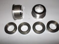
Alright, so I pulled the trigger on the staton-inc bottom bracket set-up. It consists of cups that hold two bearings in an outboard set-up.

BB cups.jpg

And a 6" (150mm) long, 17mm diameter spindle.
spindle.jpg

This should give me plenty of room to work with. If there's room to spare and the spindle feels too wide, I'll look into having someone machine me a custom one. Honestly, I don't think it'll be much of an issue since this bike is mostly a downhill and urban assault toy- no commuting here :lol:

I printed a second bearing block this last weekend, but I've incorporated a steel tube that will hold the bearings (press fit). I used a virgin plate of glass with fresh hairspray and printed it at 30% infill and ended up with significantly less edge curling.

still a little corner warp, but this is probably only 20% the warping that happened with the first block.
06032013 002.jpg

Even with this warp, my printer's z-axis is dead-nuts accurate.
06032013 005.jpg

This is the piece of cromo tube that will end up inside the plastic bearing block, still need to trim it down prior to inserting it permanently.
View attachment 3

After mocking-up the side plates on the bike, I realized I needed to change a few things. I've decreased the size of the part of the plate which bolts to the bottom bracket and shifted everything down 10mm. This drawing represents the base layer of the side plate- there will also be a second layer which will get bonded inside the depression to make everything flat. The idea being that a multilayered structure will add some strength and rigidity to the finished structure.
Kona Mid Drive Mount.jpg
 
Great project! If the mounting bracket turns out to be pretty good, but...just not "quite" strong enough (with a minor amount of flex), consider boding some aluminum plate by using DP-420 epoxy onto the sides of any section that feels like it's not as rigid as it should be. edit: just re-read your posts, saw you already mentioned adding ABS plates to stiffen :)smacks forehead:)

I just had some steel plate water-jetted by "Big Blue Saw" and I was very happy with how it turned out.

I like the entire design theme, but I am still unsure about what the top jackshaft does (currently not installed yet in pics), because the motor sprocket is on the side that it's on now?
 
spinningmagnets said:
Great project! If the mounting bracket turns out to be pretty good, but...just not "quite" strong enough (with a minor amount of flex), consider boding some aluminum plate by using DP-420 epoxy onto the sides of any section that feels like it's not as rigid as it should be. edit: just re-read your posts, saw you already mentioned adding ABS plates to stiffen :)smacks forehead:)

We're on the same page here; the first iteration of this plate set-up was sized to accommodate a 2" strip of 1/8" (3mm ish) aluminum should the plastic prove to be too flexi 8)

spinningmagnets said:
I just had some steel plate water-jetted by "Big Blue Saw" and I was very happy with how it turned out.

This is great info, thanks! For giggles, I uploaded a dxf version of the current plate to check prices- about $95 for 1-4 pieces, but only $25ish for 5-9 pieces- I could have 6 made for about $150 and have plenty of spares. This definitely beats me spending a couple hours with hand tools for a one-off that would never meet tolerances.

spinningmagnets said:
I like the entire design theme, but I am still unsure about what the top jackshaft does (currently not installed yet in pics), because the motor sprocket is on the side that it's on now?

The second or top jackshaft is where the cranks/pedal input will see another up-gearing stage to return back to a shared jackshaft (the lower one) in front of the bottom bracket. RPM's at the lower jackshaft will be right around 400 before being sent to the rear wheel for the final reduction stage via the 3-speed cassette. This is on 10s (37 volt nominal), pedals are just for show when running 20s :)

The lower jackshaft will have a 13 tooth ACS crossfire freewheel driven by the cranks, eliminating the need for a freewheeling crank. I think pics will explain this much better than I can in type, stay tuned...
 
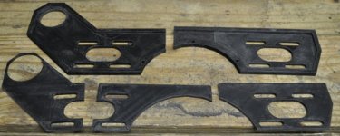
Finally printed out the final design of the side plates in 95% infill.

This is the right hand side plate in all it's component pieces: 2 base layers and 3 top layers.
ipad 003.jpg

This is the left hand plate with all pieces fitted together. I haven't yet bonded them, but everything has been sanded to fit and is ready for cementing.
ipad 005.jpg

And both pics side-by-side...
 
Dusting this back off...

I've gone through a couple different iterations since last posting (I need to snap a pic of all the assorted plastic bits related to this project, it's quite a pile :oops: ), but I think I'm finally on to a design that is both functional as well as aesthetically pleasing. At it's heart is the staton-inc bottom bracket set-up that I posted about earlier.

In it's current form, pedal power will be delivered to a jack shaft that sits on the seat tube (I've got a couple pics of this arangement in the first couple of posts on this thread) via a left sided crank. This jack shaft will then co-drive a common jackshaft that is centered on the bottom bracket spindle on the right side of the bike. The motor will also power this common jackshaft (4:1 reduction from the motor at this point) with the final reduction being performed at the rear cassette. This moves the inefficiencies to the human side (I'll be overdriving the cranks to meet the motor rpms of approx 360 at the common jack shaft which is then reduced at the rear cassette as part of the final drive reduction) and shares the highest torque reductions on the bottom bracket spindle/bearing cups where they are best handled by the bike as originally intended. Tough to explain in type, I'll post pics when I get 'em.

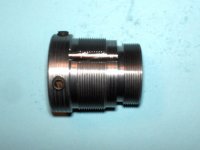
There isn't currently anything on staton-inc's website that will meet my needs in stock form, but I devised a simple way of converting a left side bottom bracket cup (1.375 x 24tpi right handed threads with space for two 30x17x7mm sealed bearings) into a 3-prong freewheel adapter. I printed out a jig that allowed me to drill the 3-prong grooves in the aluminum BB cup. You can see the jig below along with a standard adapter staton sells (5/8" w/ keyway), the stock BB cup and my modified, grooved version.
adapters.jpg
3p BB cup.jpg

I stumbled across another interesting adapter on their website that allows you to attach a second 30x1.0mm threaded freewheel to their standard 3-prong freewheel adapter. If I'm able to get the center reamed out to accept the 30mm bearings (through the larger portion of the hub), this may be a viable alternative. Might be too wide though, this is just an idea at the moment.
dual thread FW 1.jpg
dual thread FW 2.jpg

I've been printing a lot of nylon trimmer line recently and have been very impressed with it's strength and flexibility- when printed thick it can be quite rigid as well. It is also the cheapest filament I've found at approx $7 a pound when bought off of Amazon with super-saver shipping 8) . I'll be using it for the portions of this design which clamp to the bike frame, but I'll be reverting to ABS (and possibly polycarbonate in the near future) for the side plates as the flexibility of the nylon (not to mention mad- warping, it bends my glass build plate as it cools in larger pieces :shock: )makes precise postioning of the motor mount a chore.

Here are a few bottom bracket to motor mount plates, been through a few iterations to get the chain tension just right. I'll be adding a tensioner as a back-up as well.
BB motor plates.jpg
chainline.jpg

This is the controller/second motor mount with a couple brackets.


And a couple shots of the whole set-up off the bike.
View attachment 6
assembled top.jpg

I've got several tweaks to the design already in the works, but the general shape/position should remain unchanged. I'll post updates when I can.
 
Nice work, the red makes it look classy in a Ducati kind of way.
Is that made from the line trimmer (AKA whipper snipper) chord you are using in your 3D plotter?
 
jateureka said:
Nice work, the red makes it look classy in a Ducati kind of way.
Is that made from the line trimmer (AKA whipper snipper) chord you are using in your 3D plotter?

Thanks man. Whipper snipper?...you silly Aussies! :p Ya, it's lawn trimmer/edger line (we called it a weed eater or weed whacker growing up). I use stuff from amazon manufactured by maxpower, the .105" stuff consistently measures 2.67mm which feeds just dandy into my printer.
 
I finally got this thing back on the road and it's a blast. I'm running 15s lipo, so it's a little anemic in contrast to the 20s I was running last year. But at 15s, I can run 16ah in the backpack and not be too loaded down. Overall, it's a happy compromise (max theoretical power near 2500 watts with my 40 amp controller). Unfortunately, my CA is dead at the moment so I don't have solid data on power/speed.

This is the heart of the reduction scheme. At this point the pedal crank input from the human side meets the motor input at the first motor reduction stage. This makes it a very inefficient pedal bike, but this is in all honesty a pedal-assisted electric bike and not the other way around :) . Output to the rear cluster is from a 16 tooth main driver which allows a the secondary motor reduction to happen at the rear gear cluster on the bike. So far, I've had absolutely ZERO chain skip at the rear gears- something that was happening very regularly with my traditional free-wheeling crank system on the previous version. This is likely due to being able to use only larger cogs in the back.

20131117_155912.jpg

20131117_155924.jpg

Out the window went my KISS (keep it simple, stupid) principle with this seat tube mounted jack shaft. I call it the meat grinder, but so far I've kept my digits/extremities out of the mechanism and only slightly chewed up some pant cuffs- the price of progress. I've got aspirations of designing a planetary gear system that will accomplish the same thing (elevating pedal input RPMs to motor RPMs), but that is way out in the future at this point.

20131117_155711.jpg

20131117_155732.jpg

Running a WTB 2.4 velociraptor caused the black marks on the block in this photo when near bottoming the suspension. I changed to a 2.3 krad, trimmed the bolts and tightened the pre-load on the rear spring and I haven't had any bad noises from this mount yet. I've got plans to move this jack shaft lower towards the bottom bracket on version 2.0 which will get it out of the way of any size tire. I'm very happy with the strength of this mount, plastic for the win.

20131117_221134.jpg

I was losing the chain off the front driver sprocket, so I came up with this little add-on chain guide/keeper- so far, it's been perfect. I was also expecting to have to add a guide or scuff plate to the rear chain stay (at least on the bottom) where the chain crosses since I went with a much smaller front sprocket than is standard on a bicycle, but there hasn't been excessive chain slap at this location. It may be drowned out from all the other rotating chain/freewheel noises though- far from silent this one is, looking for stealth? This is not it :lol:

20131117_155656.jpg

I also changed up the front motor/controller mount to make use of some existing mounting holes on the case of the motor- very solid, no discernible flex.

20131117_155823.jpg

And here are a few pics of the bike at this stage. I'll eventually get box/enclosure printed up to hide the controller connection wires, but for now the stretchy velcro wraps will have to suffice 8). I've got a vid of it running on the stand with a little walk-around of the drive mechanism I'll get uploaded in the next day or two. I'll shoot some actual riding vids in the near future as well (not making any guarantees as my update track record is suspect at best :lol: )

DSC_0120.JPG

View attachment 3

DSC_0123.JPG

DSC_0125.JPG

DSC_0126.JPG
 
This is a quick and dirty edit using phone software so please excuse the quality. There are several examples of unpowered vs powered chain noise to give you an idea of actual sound. As usual, high frequencies are amplified on the vid, it's not really that loud in person- not silent, but not full RC either. I pledge to post actual riding video in the near future 8)

[youtube]UBgo6NMlMOc[/youtube]
 
I'm now running a 3 speed rear cluster that is shifted via a standard front chainring trigger shifter. For each gear change from the front shifter, the rear derailleur moves two cogs, so I modified a rear cassette down to 5 cogs (6 if you count the 11 tooth I had to leave on for the locking mechanism, but it doesn't see drive) with the three drive cogs being 34, 26 and 16 teeth. By reducing the cogs in the cassette, I was able to space the entire cluster over to allow for a perfect chainline on the largest, highest torque cog.

I've been running a similar set-up on a pedal bike, but that cassette only has 3 cogs so the spacing is large enough for the chain to drop between cogs on missed shifts. By leaving the two "spacer" cogs on the rear, they help the rear derailleur shift and any cog jumps quickly re-find their home without losing the chain. Overall, I'm happy with this set-up- it simplifies the gearing options and makes it easier to know exactly what gear you are in since there are only three.

DSC_0130.JPG

Another short-fall of my current bottom bracket to motor mounting plates is their lack of adjustability. When I first mounted the chain, tension was perfect. But now, as the chain wears in and the mounts shift (tenths of millimeters of movement here add up to significant chain slack over such a short run of chain I've found) there's too much slack in the first reduction chain. I drew inspiration from the RepRap world where many of the home-brew machines are made of threaded rod frames.

Adjustable BB to GM500 Mount LEFT.jpg

Adjustable BB to GM500 Mount RIGHT.jpg

By using a piece of threaded 5/16" rod between the plastic bottom bracket and motor mounts, I'll be able to adjust tension with ease. Here they are still on the mirrored tiles I use on my printer (the top two pieces were a first print rough draft).
DSC_0127.JPG

And after removing from the tiles and separating the brim. I also incorporated the front drive chainring keeper into the bottom bracket mount to simplify things.

View attachment 1

I also redesigned the seat tube jackshaft mounting plates which should allow me to move the entire seat tube jackshaft assembly down and out of the way of the rear tire completely, allowing use of fatter rubber.

ST JS Bearing Plates.jpg
 
Got the adjustable bottom bracket to motor mount plates on and they work as expected. I changed the gearing on the 1st reduction from 9:36 to 9:44, I think this is the sweet spot for this rig in the dirt. Tops out a touch over 30mph in high gear on 15s lipo. I've got plans to change the primary reduction over to #25 chain (the 44 tooth bike sprocket is too large- it functions fine, but looks too big 8) ), but I'll have to file the shaft down on the motor (probably go to 1/2" standard since I can get these easily from Mcmaster) as I can't find any 14mm ID sprockets. A project for a colder day perhaps.

Adj MM parts[1].JPG

View attachment 6

Adj mount 2[1].JPG

Adj mount 3[1].JPG

This is my "rough draft" for a frame mounted battery solution. This is stage 1 to figure out placement and then I'll start bodging a solution to enclose this thing. As it sitsm the batteries are very secure with these velco straps, but they're vulnerable to side impact/puncture/abrasion. I envision 1/4" polycarbonate side plates that hinge on the same threaded rod the velcro mounts to. I also plan to eventually print some nice front, rear and top caps to make it look a little less cobbled together.

But, for now, function over form! It's nice to get the batteries out of the backpack and back onto the frame.

Batt Mount 1[1].JPG

Batt Mount 2[1].JPG

Batt Mount 3[1].JPG

 
Nice.
Any reason you went with 15S lipo?
 
jateureka said:
Nice.
Any reason you went with 15S lipo?

Mainly it's what I had on hand. Much better than 10s, but not as good as 20s- so it's a compromise. I may try to cram another two packs in the triangle for 20s 16ah- I'm sure I'll cook the motor with that much energy on board. That reminds me, I need to hook up that thermometer...
 
This build is super cool! I haven't seen a whole lot of people use this thorough of a 3DPrinted assembly for an ebike project. And I always thought the nylon weed-whacker line was a joke, didn't think anybody actually used it.

I have almost the same bike (2001 Kona Stinky Deelux, 17") and I also have a BLT-500 I was going to use for a mid-drive Yuba. Any chance you'd share your CAD files, or maybe even just your .STLs? I might be able to add a couple features or help with some shrouds/weatherizations, and I'd share back your direction, too, if I did. I use Thingiverse a lot, so I like the share/improve/reshare format for projects.

Just wondering, and great job.
 
Back
Top