KT-22A / LCD8H PAS

Cockrobin

100 µW
Joined
Apr 22, 2023
Messages
8
Location
Cornwall
Hi, My first question on the forum.
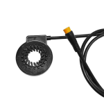
I have a KT-22A / LCD8H controller / display diving a Bafang RM G020 500W hub motor, using a 52V 13Ah battery. All is working apart from the PAS, which has never worked. The supplier sent a chain ring side PAS sensor which cannot be fited to the bike unless I change the chain ring for a single speed type. I got a KT-V12L left hand crank sensor which is self contained and tucks into the bottom bracket retaining collar- 1684774567550.png
I have tried to change LCD8H display settings but can't find a combination that works.

The PAS connects directly to the KT-22A controller. I have made a brekout cable and the +5V supply seems to be present, just that nothing appears on the signal line. Borrowed a friends simple split type sensor and got no joy from that either. (Though he does have a different controller type)

I have looked far and wide but can't find any advice for this. The kit supplier has been useless. It would be really handy to find detailed wiring diagrams for the KT-22A and the KT-V12L.

Out of ideas, can anyone help?
 
I shall go and check C1 again. I'm sure I tried all the C1 options but worth another pop.
Reason I ask about wiring is that I bought a3-way extension cable and split it to make the break out. The wire colours are Red Black and White. When I put a meter across the Red and Black wires I get -5V, which is not what I expected. I have assumed the KT-22A wiring is correct but it oesn't look right. I buzzed the pins throuh the extension cable and they line up as expected with the controller connector socket. Next step is to disassemble the controller housing and check what is going on inside it. I was really hoping not to have to do this. The harness took ages to get tidy but hey-ho. :)
 
Last edited:
The PAS connects directly to the KT-22A controller. I have made a brekout cable and the +5V supply seems to be present, just that nothing appears on the signal line. Borrowed a friends simple split type sensor and got no joy from that either.
If nothing appears on the output, can you try running the sensor disconnected from the controller, from a separate 5v supply (usb-type charger, etc)? Or cut the signal wire on the breakout cable and measure only on the sensor side. This is to make sure there's nothing on the controller end grounding hte signal (internal miswire, etc). Also make sure the sensor is actually wired as expected--that the 5v is going to the sensor's 5v input, etc.

If you are certain the sensor is getting power and ground correctly, and it's output still has no signal, regardless of rotation direction, the sensor is probably defective in some way.

If you still have the sensor that won't fit on the bike you can test using that, setting it up the same way and seeing if you get a signal manually rotating the sensor's magnet wheel (the wheel probably has to be held to about 5mm from it, no closer, maybe 10mm max, and rotated in the correct direction relative to the sensor). If it does work, hook it up to the controller, and see if it lets the motor run (driven wheel offground).

If it does, then no need to mess with the controller--it's just a bad sensor you can then replace.

BTW, if the reason you can't use that sensor is the magnet ring won't fit on the crankshaft you can pop the magnets out and glue them to the inner chainring at the right diameter circle to match the plastic ring, and put the sensor at the right distance from them.
 
You should actually measure the voltage on all three pins. As PAS is digital input it has power, gnd and input sensing that usually connected to pull-up resistor meaning it will have voltage on it. Easiest way to find if PAS is working is to use 5-10kOhm resistor and try connect GND pin to one of other pin. If you measure then the voltage between resistor legs: the one port that gives 0V is your PAS input. The one that holds the voltage well above like 3,5V to nearly 5V is your power pin. PAS is detecting low voltage drop to zero so try shorting GND pin to input pin via that resistor in short pulses. If you find proper pulse proportions you may be able to activate motor with suche pulses.
PS wire colors can be actually missleading .
Great advice szkuba, and from amberwolf and AGS. Interesting note abot wire colours. A decent schematic for the controller would be useful.

Other project have intervened, and I can zing along on the throttle for now. I will get back on to this though Many thanks.
 
Hi Folks. Problem solved.

There is an odd mismatch between the PA Sensor connector pinning and the controller pinning. I now have 3 similar PAS senosors and they all work once the wiring is modified. I worked through the problem as advised by szkuba. The controller was easy enough. The PA sensor not so easy. Luckily I had a bench power supply to hand and could deliver current limited +5V. It was a question of seeing a sensible power draw and looking at the third pin with an oscilloscope while the sensor was activated.

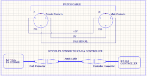
When I found the correct connector pinnings I took a Joliet extension cable, split it and patched the signals across. I lashed it together to test the new connections and when that worked made up a short patch cable to insert between the controller and the PAS. The C1 parameter, set with the LCD8H display, needs to be 07.

The bit I don't get is that both PAS and controller seem to be made by Kunteng. They both have the KT- part prefix. Why on earth should they be incompatible?

BTW this mod also works for a KT-D12L split magnet ring sensor.

The neat solution would be to open up the controller and rewire it from the inside. Also, it is possible that my controller has been wrongly wired and this is just my problem. However, I have attached a schematic of the patch cable in a Word document in case the issue comes up for anyone else:-
(I tried to paste from the clipboard but I'm afraid the quality was rubbish.)

EDIT - Had a bright idea and used the Windows sniping tool for a screenshot... doh.

1689157754745.png
 

Attachments

  • PAS-Patch.docx
    16.1 KB · Views: 6
Last edited:
Hi, My first question on the forum.
I have a KT-22A / LCD8H controller / display diving a Bafang RM G020 500W hub motor, using a 52V 13Ah battery. All is working apart from the PAS, which has never worked. The supplier sent a chain ring side PAS sensor which cannot be fited to the bike unless I change the chain ring for a single speed type. I got a KT-V12L left hand crank sensor which is self contained and tucks into the bottom bracket retaining collar- View attachment 334427

I have tried to change LCD8H display settings but can't find a combination that works.

The PAS connects directly to the KT-22A controller. I have made a brekout cable and the +5V supply seems to be present, just that nothing appears on the signal line. Borrowed a friends simple split type sensor and got no joy from that either. (Though he does have a different controller type)

I have looked far and wide but can't find any advice for this. The kit supplier has been useless. It would be really handy to find detailed wiring diagrams for the KT-22A and the KT-V12L.

Out of ideas, can anyone help?
Not sure if you solved the issue. I had similar issue with a PAS replacement kit bought online. What I did was I kept the red wire to red, and then switch the other 2 wires around and it works. Somehow the PAS kicks in when I pedal forward and backwards after I did the wire switch. If it works for you, just becareful when you back pedal.
 
Back
Top