KT motor controllers -- Flexible OpenSource firmware for BMSBattery S/Kunteng KT motor controllers (0.25kW up to 5kW)

Basia said:
casainho said:
Basia said:
casainho said:
I am losting my time while you don't follow only the config-example.h.

I deleted this code and the throttle is working fine but the maximum speed has decreased to 35km/h
Verify if MOTOR_ROTOR_OFFSET_ANGLE is the best possible and aslo what should be the ERPs speed at that 35km/h, can't be higher than 525.
why this code reduces the maximum speed by 20-25 km/h? with this code speed 55-57
I can not find another angle of the motor. well working angles can be multiple?
Angle should be near 0 but can be a value between 0 and 255. If you put 512 is the same as 255.
 
casainho said:
Seems logic that we need to look a current direction/signal. I think that I saw phase current signal invert 180 degrees when braking and if that happens, so mantain the same logic for increase/decrease the angle will mean that will work as expect. On current code I invert the logic of increasing/decreasing the angle when regen and so that is why it should run away from the correct value.

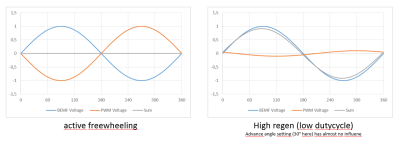
You are right, but again, you can't influence the phase shift of the phase current at high regen, say low duty cycle.
I don't know if this sketch is correct, but that's my understanding at the moment. BEMF Voltage is always in Phase with rotor, the current has a phase shift, depending on speed and load.
You can play around with the excel file a little.

regards
stancecoke

BEMF voltage vs. PWM voltage.PNG
 
I chose the angle step by step through 0 to 100 degrees and from 0 to -100. the best value of 131, works quietly and smoothly. the motor does not stop until the end and the rotation in the opposite direction.
[youtube]Mh4OWyZn0b0[/youtube]
 

Attachments

  • config.h
    1.3 KB · Views: 48
Basia said:
I chose the angle step by step through 0 to 100 degrees and from 0 to -100. the best value of 131, works quietly and smoothly. the motor does not stop until the end and the rotation in the opposite direction.
[youtube]Mh4OWyZn0b0[/youtube]
So the only left issue is the rotation direction.

Did you follow the the phases and hall sensors correct connection on the documentation? If they are correct, I think you will need to try and you should find a combination that will spin the motor on the other direction. An then the angle will be near 0.
 
casainho said:
Basia said:
I chose the angle step by step through 0 to 100 degrees and from 0 to -100. the best value of 131, works quietly and smoothly. the motor does not stop until the end and the rotation in the opposite direction.
[youtube]Mh4OWyZn0b0[/youtube]
So the only left issue is the rotation direction.

Did you follow the the phases and hall sensors correct connection on the documentation? If they are correct, I think you will need to try and you should find a combination that will spin the motor on the other direction. An then the angle will be near 0.

on stock firmware, the wheel rotated in the forward direction.
Now, to select another combination of phases and Hall sensors, I need to know the angle at which the wheel will rotate in the forward direction. :(
 
Angle will be 0 or very near 0. Start with 0.
 
casainho said:
Angle will be 0 or very near 0. Start with 0.

what is 2 6 4 5 1 3?
2 | 0 volts | 5 volts | 0 volts
6 | 5 volts | 5 volts | 0 volts
4 | 5 volts | 0 volts | 0 volts
5 | 5 volts | 0 volts | 5 volts
1 | 0 volts | 0 volts | 5 volts
3 | 0 volts | 5 volts | 5 volts

first signal 1 then 2, etc. or 2 then 6 further down the list?
 
Basia said:
casainho said:
Angle will be 0 or very near 0. Start with 0.

what is 2 6 4 5 1 3?
2 | 0 volts | 5 volts | 0 volts
6 | 5 volts | 5 volts | 0 volts
4 | 5 volts | 0 volts | 0 volts
5 | 5 volts | 0 volts | 5 volts
1 | 0 volts | 0 volts | 5 volts
3 | 0 volts | 5 volts | 5 volts

first signal 1 then 2, etc. or 2 then 6 further down the list?
Well, seems that numbering is a problem, I will improve that later.

Use this table for now:
1 | 0 volts | 5 volts | 0 volts
2 | 5 volts | 5 volts | 0 volts
3 | 5 volts | 0 volts | 0 volts
4 | 5 volts | 0 volts | 5 volts
5 | 0 volts | 0 volts | 5 volts
6 | 0 volts | 5 volts | 5 volts

test and tell us what is the sequence. For it to work, it should be: 1, 2, 3, 4, 5, 6
 
casainho said:
Basia said:
casainho said:
Angle will be 0 or very near 0. Start with 0.

what is 2 6 4 5 1 3?
2 | 0 volts | 5 volts | 0 volts
6 | 5 volts | 5 volts | 0 volts
4 | 5 volts | 0 volts | 0 volts
5 | 5 volts | 0 volts | 5 volts
1 | 0 volts | 0 volts | 5 volts
3 | 0 volts | 5 volts | 5 volts

first signal 1 then 2, etc. or 2 then 6 further down the list?
Well, seems that numbering is a problem, I will improve that later.

Use this table for now:
1 | 0 volts | 5 volts | 0 volts
2 | 5 volts | 5 volts | 0 volts
3 | 5 volts | 0 volts | 0 volts
4 | 5 volts | 0 volts | 5 volts
5 | 0 volts | 0 volts | 5 volts
6 | 0 volts | 5 volts | 5 volts

test and tell us what is the sequence. For it to work, it should be: 1, 2, 3, 4, 5, 6

ABC or CBA ?

My configuration

Blue. Green. Yellow

0 5 0 - 1
5 5 0 - 2
5 0 0 - 3
5 0 5 - 4
0 0 5 - 5
0 5 5 - 6

does the wheel need to rotate in the backward direction ?
 
Basia said:
does the wheel need to rotate in the backward direction ?
Hall sensor connections

With the motor phase wires disconnected (it is recommended to insulate with tape the phase wires) and the hall sensor wires connected to the motor controller, use a multimeter to measure the voltage of each hall sensor wires.

Rotate the wheel slowly by hand in the backward direction and the motor will rotate (if you are using a geared motor, it is the only direction which the motor will rotate).

For the hall sensors to be correctly connected, you must make sure the voltages sequence is the following (and repeats over and over) - if not, you will need to exchange the wires up to get the right sequence:

Position | Blue wire: hall sensor C | Green wire: hall sensor B | Yellow wire: hall sensor A
1 | 0 volts | 5 volts | 0 volts
2 | 5 volts | 5 volts | 0 volts
3 | 5 volts | 0 volts | 0 volts
4 | 5 volts | 0 volts | 5 volts
5 | 0 volts | 0 volts | 5 volts
6 | 0 volts | 5 volts | 5 volts
 
Yellow. Green. Blue. ? Or Blue. Green. Yellow?
1 | 0 volts | 5 volts | 0 volts
2 | 5 volts | 5 volts | 0 volts
3 | 5 volts | 0 volts | 0 volts
4 | 5 volts | 0 volts | 5 volts
5 | 0 volts | 0 volts | 5 volts
6 | 0 volts | 5 volts | 5 volts

I chose the right combination!
I changed the phase wires yellow-yellow green-blue and blue-green.
Hall sensors changed the yellow-blue green-green blue-yellow.
the direction of rotation is correct
the correct angle is not near 0
 
Basia said:
Yellow. Green. Blue. ? Or Blue. Green. Yellow?
1 | 0 volts | 5 volts | 0 volts
2 | 5 volts | 5 volts | 0 volts
3 | 5 volts | 0 volts | 0 volts
4 | 5 volts | 0 volts | 5 volts
5 | 0 volts | 0 volts | 5 volts
6 | 0 volts | 5 volts | 5 volts

I chose the right combination!
I changed the phase wires yellow-yellow green-blue and blue-green.
Hall sensors changed the yellow-blue green-green blue-yellow.
the direction of rotation is correct
the correct angle is not near 0

no one will answer my question?
 
Basia said:
Basia said:
Yellow. Green. Blue. ? Or Blue. Green. Yellow?
1 | 0 volts | 5 volts | 0 volts
2 | 5 volts | 5 volts | 0 volts
3 | 5 volts | 0 volts | 0 volts
4 | 5 volts | 0 volts | 5 volts
5 | 0 volts | 0 volts | 5 volts
6 | 0 volts | 5 volts | 5 volts

I chose the right combination!
I changed the phase wires yellow-yellow green-blue and blue-green.
Hall sensors changed the yellow-blue green-green blue-yellow.
the direction of rotation is correct
the correct angle is not near 0

no one will answer my question?
So,
1. did you get it to run to the direction you wanted?
2. If so, what was the best angle?
3. And do you think is running using low/regular current or not?
 
casainho said:
Basia said:
Basia said:
Yellow. Green. Blue. ? Or Blue. Green. Yellow?
1 | 0 volts | 5 volts | 0 volts
2 | 5 volts | 5 volts | 0 volts
3 | 5 volts | 0 volts | 0 volts
4 | 5 volts | 0 volts | 5 volts
5 | 0 volts | 0 volts | 5 volts
6 | 0 volts | 5 volts | 5 volts

I chose the right combination!
I changed the phase wires yellow-yellow green-blue and blue-green.
Hall sensors changed the yellow-blue green-green blue-yellow.
the direction of rotation is correct
the correct angle is not near 0

no one will answer my question?
So,
1. did you get it to run to the direction you wanted?
2. If so, what was the best angle?
3. And do you think is running using low/regular current or not?

1 - yes
2 - no
offset angle and interpolation 60 - 0 degrees. but this is not a sine wave (
maximum speed not constant. the current varies from 1.3A to 2A
 
Basia said:
offset angle and interpolation 60 - 0 degrees.

See the instructions in the config-example.h
Code:
// This value is ERPS speed after which a transition happens from sinewave no interpolation to have
// interpolation 60 degrees and must be found experimentally but a value of 25 may be good
#define MOTOR_ROTOR_ERPS_START_INTERPOLATION_60_DEGREES 25

The interpolation start should not be zero. For a direct drive it should be lower than for a geared motor. I use the value "4" for my BionX DD.


Basia said:
but this is not a sine wave

How did you come to this statement? Have you checked the phase current with an oszilloscope?!

regards
stancecoke
 
stancecoke said:
Basia said:
offset angle and interpolation 60 - 0 degrees.

See the instructions in the config-example.h
Code:
// This value is ERPS speed after which a transition happens from sinewave no interpolation to have
// interpolation 60 degrees and must be found experimentally but a value of 25 may be good
#define MOTOR_ROTOR_ERPS_START_INTERPOLATION_60_DEGREES 25

The interpolation start should not be zero. For a direct drive it should be lower than for a geared motor. I use the value "4" for my BionX DD.


Basia said:
but this is not a sine wave

How did you come to this statement? Have you checked the phase current with an oszilloscope?!

regards
stancecoke

what is your offset angle?
 
Basia said:
what is your offset angle?

I use the firmware version from my own fork. Here the advance angle and the offset angle are defined from a different base, so the values are not comparable...

https://github.com/stancecoke/BMSBattery_S_controllers_firmware

regards
stancecoke
 
Basia said:
casainho said:
Basia said:
Basia said:
Yellow. Green. Blue. ? Or Blue. Green. Yellow?
1 | 0 volts | 5 volts | 0 volts
2 | 5 volts | 5 volts | 0 volts
3 | 5 volts | 0 volts | 0 volts
4 | 5 volts | 0 volts | 5 volts
5 | 0 volts | 0 volts | 5 volts
6 | 0 volts | 5 volts | 5 volts

I chose the right combination!
I changed the phase wires yellow-yellow green-blue and blue-green.
Hall sensors changed the yellow-blue green-green blue-yellow.
the direction of rotation is correct
the correct angle is not near 0

no one will answer my question?
So,
1. did you get it to run to the direction you wanted?
2. If so, what was the best angle?
3. And do you think is running using low/regular current or not?

1 - yes
2 - no
offset angle and interpolation 60 - 0 degrees. but this is not a sine wave (
maximum speed not constant. the current varies from 1.3A to 2A
So, for what I could understand, the firmware works well (your motor running smoothly and asking low current) BUT runs in the opposite direction you need.

Up to now, our developed firmware always did run on the needed direction for ebike motors and so we don't have experience to make it run motors on the other direction, like you need to for your electric kick scooter.
The only possibility I see that hopefully will work, is to find a different combination of hall sensors and phase wiring. Also the MOTOR_ROTOR_OFFSET_ANGLE may need to have a different value from 0 (from 0 up to 255).
 
Regen disable
[youtube]JkIL-AzRZys[/youtube]

Regen enable
[youtube]FdvNRbqbD6E[/youtube]

motor does not start with regen enabled

you do not know what phase settings are in the standard firmware setting C2? I worked well with the C2-2 setup
 

Attachments

  • config.h
    1.4 KB · Views: 35
regen is implemented in a very special way in the firmware.
https://opensourceebikefirmware.bitbucket.io/development/Various--2017.12.01_-_Regen_ebrake_like_coast_brakes.html

It is activated by pedaling in reverse and you have to solder an additional wire to the controllers pcb.

With my fork you can activate stepless regen with a modified brake lever or an additional thumb throttle, but it needs the additional wire too.

We could easily implement constant regen activated by the brake lever switch, but nobody asked for that so far.

regards
stancecoke
 
stancecoke said:
We could easily implement constant regen activated by the brake lever switch, but nobody asked for that so far.
That is already implemented on current firmware and that is how I am being testing regen. When brakes are activated, battery regen current is set to ADC_BATTERY_REGEN_CURRENT_MAX and target duty_cycle is set to 0:

Code:
// Brake signal
void EXTI_PORTA_IRQHandler(void) __interrupt(EXTI_PORTA_IRQHANDLER)
{
  if (brake_is_set())
  {
    motor_controller_set_state (MOTOR_CONTROLLER_STATE_BRAKE);
    ebike_app_battery_set_regen_current_max (ADC_BATTERY_REGEN_CURRENT_MAX);
    motor_set_regen_current_max (ADC_MOTOR_REGEN_CURRENT_MAX);
    motor_set_pwm_duty_cycle_target (0);
    ebike_app_cruise_control_stop ();
    ebike_app_set_state (EBIKE_APP_STATE_MOTOR_STOP);
  }
  else
  {
    motor_set_regen_current_max (0);
    ebike_app_battery_set_regen_current_max (0);
    ebike_app_set_state (EBIKE_APP_STATE_MOTOR_STOP);
    motor_controller_reset_state (MOTOR_CONTROLLER_STATE_BRAKE);
#if defined (EBIKE_REGEN_EBRAKE_LIKE_COAST_BRAKES)
    motor_reset_regen_ebrake_like_coast_brakes ();
#endif
  }
}
 
perhaps I need to remove the extra settings from config.h. pas, etc. ? I have only a brake and thtottle. what else can you think of to simplify the settings?
 
casainho said:
stancecoke said:
We could easily implement constant regen activated by the brake lever switch, but nobody asked for that so far.
That is already implemented on current firmware and that is how I am being testing regen. When brakes are activated, battery regen current is set to ADC_BATTERY_REGEN_CURRENT_MAX and target duty_cycle is set to 0:

Ah, nice to see, I didn't knew that :)

But if you set target duty_cycle to zero, you have to disable FOC at regen, otherwise the advance angle runs to nirvana, see the posts before.

regards
stancecoke
 
stancecoke said:
But if you set target duty_cycle to zero, you have to disable FOC at regen, otherwise the advance angle runs to nirvana, see the posts before.
That is what I am trying to solve. The Android app you did recommend works very well and will help me on this!! Thanks.
 
Basia said:
perhaps I need to remove the extra settings from config.h. pas, etc. ? I have only a brake and thtottle. what else can you think of to simplify the settings?
The issue about the motor, I think is nothing about regen. Or you find a good working hall sensor and phase wire combinations or the firmware simple won't work for you. Other option would be to develop the firmware and make an option on config.h for motor rotation direction -- I am busy with other things and I am not really motivated to work on that.
 
Back
Top