KT motor controllers -- Flexible OpenSource firmware for BMSBattery S/Kunteng KT motor controllers (0.25kW up to 5kW)

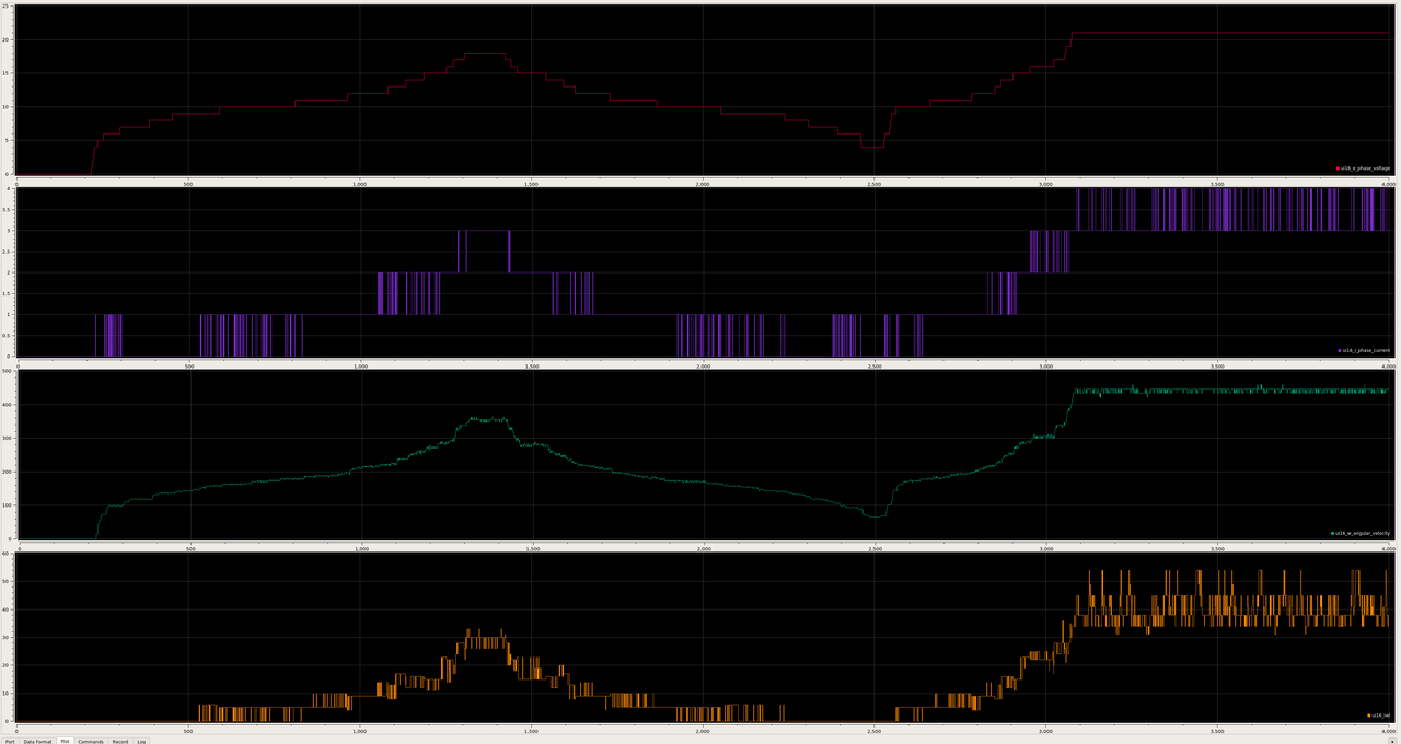
For knowledge, please see calculation of FOC angle using motor inductance and not phase current -- this is an early experiment but seems to be inline of what we expect:

casainho said:
Got an experimental code working near what is expected - I will explain:

On purpose, I put an wrong angle value at startup and I see my motor asking to much current when I increase the speed. When I put a correct value of 0, it simple don't ask much current is about 0.6 amps on full speed and I think that is because it has low current/load.

So I put an angle of 10: #define MOTOR_ROTOR_OFFSET_ANGLE 10

Here the the experimental code, that calcs Iwl and V, than it does asinf and convert to angle values. Yes, I think some part of the code may not doing correct angle conversion.... can you please review?

The code prints the variables and also puts the negative value to ui8_angle_correction, that is used to correct the angle.

I did 2 tests, by keeping the ui8_angle_correction always at 0 (angle offset error of 10) or by apply the value calculated. I show t
he graphs and logged as also videos, where you can see the power supply current for each case and listen the motor noise.

Code:
  ui32_l_x1000000 = 135;

  ui32_temp = ui32_w_angular_velocity_x10 * ui32_l_x1000000;
  ui32_temp *= ui32_i_phase_current_x2;
  ui16_iwl = (ui32_temp / 2000000);
  
  f_temp = asinf((float) ui16_iwl / (float) ui16_e_phase_voltage) * 5732.0;
  ui16_temp = f_temp;

  printf ("%d,%d,%d,%d\n",
          ui16_e_phase_voltage,
          ui16_i_phase_current,
          ui16_motor_speed_erps,
          ui16_temp/100);

  ui8_angle_correction = - (ui16_temp/100);

FOC calculation disabled:
- speed ERPS = 450
- phase current = 3.5A

FOC calculation enabled:
- speed ERPS = 350
- phase current = 0.5A

FOC calculation disabled


FOC calculation enabled


FOC calculation disabled
[youtube]-cUIJlzcs2c[/youtube]

FOC calculation enabled
[youtube]8uOsVOv5oS4[/youtube]
 
Valopallo said:
Is it possible to turn on the S06S(or other KT/BMSBattery controllers) without the ON -button of LCD or LED?

You just have to short the blue wire of the Display connector to the red wire to switch on the system.

regards
stancecoke
 
casainho said:
For knowledge, please see calculation of FOC angle using motor inductance and not phase current

I think, this will not help, as we can't influence the phase shift of the phase current with the advance angle at low duty cycle values.

I am interested in the correlation between the cuty cycle and the voltage step up converter effect.
For active freewheeling, we control the battery current to be zero. In this case the PWM battery voltage is same as the back emf.
If we decrease the duty cycle from this point, we get regen and brake the rotor. If we increase duty cycle we get motor mode and accelerate the rotor.

But what is the dutycycle where we get the best step-up-converter-effect to amplify the back-emf voltage?? I don't understand that actually. :(

regards
stancecoke
 
stancecoke said:
Valopallo said:
Is it possible to turn on the S06S(or other KT/BMSBattery controllers) without the ON -button of LCD or LED?

You just have to short the blue wire of the Display connector to the red wire to switch on the system.

regards
stancecoke

Ok. So, when the blue wire and the red wire are connected, shouldn't there be a +5V reading from some of those display wires? I'm starting to think my controller is not working properly...
 
stancecoke said:
casainho said:
For knowledge, please see calculation of FOC angle using motor inductance and not phase current

I think, this will not help, as we can't influence the phase shift of the phase current with the advance angle at low duty cycle values.
That was out of this topic. Was more to be aware that maybe on KT and TSDZ2, maybe we can implement FOC without using the phase current sensor. But nothing really important for KT.

stancecoke said:
I am interested in the correlation between the cuty cycle and the voltage step up converter effect.
For active freewheeling, we control the battery current to be zero. In this case the PWM battery voltage is same as the back emf.
If we decrease the duty cycle from this point, we get regen and brake the rotor. If we increase duty cycle we get motor mode and accelerate the rotor.
Correct. I understand like that also.

stancecoke said:
But what is the dutycycle where we get the best step-up-converter-effect to amplify the back-emf voltage?? I don't understand that actually. :(
I am not sure I can follow/understand you.

Amplify the back-emf voltage?? but on your tests, the regen/brake does not work? is that strong or not? or is strong but you only see little current flowing to battery?
 
Valopallo said:
Ok. So, when the blue wire and the red wire are connected, shouldn't there be a +5V reading from some of those display wires? I'm starting to think my controller is not working properly...

??? You wrote that you have a Bafang Controller?!
I don't know, if this is switched on in the same way as the Kuntengs.
At Kunteng there is no 5V line at the display connector
red: +36V
black: gnd
blue: ignition
yellow: rx
green: tx

5V can be found at the throttle or PAS-Connecor, when the system is switched on.

regards
stancecoke
 
casainho said:
Amplify the back-emf voltage??

The DC-Rail voltage has to be higher than the Battery voltage, otherwise the current cannot flow backwards...

casainho said:
but on your tests, the regen/brake does not work? is that strong or not? or is strong but you only see little current flowing to battery?

If you look at the red line in the graph, it has a battery current of 283 = -2,9Amps. So you can get significant regent current. The braking effect is quite low. Therefore I think the regen current can be improved somehow.

I'm planning to test this things at the testbench:

1. keeping erps and dutycycle constant, adjust advance angle to optimum battery current
2. keeping erps and advane angle constant, adjust the dutycycle to optimum battery current

regards
stancecoke
 
stancecoke said:
casainho said:
Amplify the back-emf voltage??

The DC-Rail voltage has to be higher than the Battery voltage, otherwise the current cannot flow backwards...
Don't know if you mean BEMF voltage when you say DC-rail. As I see, we don't amplify BEMF voltage but instead reduce battery phase voltage by reducing the duty-cyle and so that way the current will flow to battery.
 
Seems that you have the old release of SDCC installed.

make sure, that you use this:
https://sourceforge.net/projects/stm8-binutils-gdb/files/cygwin/x86_64/release/sdcc/sdcc-3.7.0-1.tar.xz/download

And der Path information (first line of the log) seems to be faulty.


regards
stancecoke
 
stancecoke said:
I'm planning to test this things at the testbench:

1. keeping erps and dutycycle constant, adjust advance angle to optimum battery current
2. keeping erps and advane angle constant, adjust the dutycycle to optimum battery current

I've done the first test series now.
In hindsight, the result is logical. The lower the duty cycle, the less influence the advance angle has on the phase current shift. The highest regen current you get with duty cycle = 0. I can only test at low powers as my lab power supply only allows 5 amps for the middrive motor that drives the direct drive hub motor.
With lower duty cycles the erps drop a little, as the load increases.

regards
stancecoke

advance angle influence at different duty cycles.PNG
 
stancecoke said:
stancecoke said:
I'm planning to test this things at the testbench:

1. keeping erps and dutycycle constant, adjust advance angle to optimum battery current
2. keeping erps and advane angle constant, adjust the dutycycle to optimum battery current

I've done the first test series now.
In hindsight, the result is logical. The lower the duty cycle, the less influence the advance angle has on the phase current shift. The highest regen current you get with duty cycle = 0. I can only test at low powers as my lab power supply only allows 5 amps for the middrive motor that drives the direct drive hub motor.
With lower duty cycles the erps drop a little, as the load increases.
Unfortunately I can't understand/follow some parts that you saying.

Last time I tried to real time log with Bluetooth for Android, I couldn't find an app that continuously log as soon the app gets in background... If you use one app, can you recommend?
 
Basia said:
need to copy the usr folder to c:\sdcc? nothing has changed in the logs.
You have to delete the old version first.
The path has to be the same as in the fist line of the start_compiling.bat

Code:
PATH = %PATH%;C:\Program Files (x86)\STMicroelectronics\st_toolset\stvp;C:\SDCC\usr\local\bin;%~p0\tools\cygwin\bin

the command "%~p0" seems not to work with your windows installation, try to edit the start_compiling.bat manually according to your folder system.

regards
stancecoke
 
casainho said:
Last time I tried to real time log with Bluetooth for Android, I couldn't find an app that continuously log as soon the app gets in background... If you use one app, can you recommend?

I use BlueTerm from the play store. It's very simple but works reliably.

regards
stancecoke
 
the firmware was a success! I chose the angle of the motor 131 ^ but it rotates in the opposite direction. to choose another angle?
at an angle of 131, the wheel rotates slower than at an angle of 135. at 131 angle the battery current is 0.6A and at 135 angle - 2.5A

maybe there is information about the angle of the standard firmware? on the standard firmware my wheel was spinning very well.
 
stancecoke said:
Valopallo said:
Ok. So, when the blue wire and the red wire are connected, shouldn't there be a +5V reading from some of those display wires? I'm starting to think my controller is not working properly...

??? You wrote that you have a Bafang Controller?!
I don't know, if this is switched on in the same way as the Kuntengs.
At Kunteng there is no 5V line at the display connector
red: +36V
black: gnd
blue: ignition
yellow: rx
green: tx

5V can be found at the throttle or PAS-Connecor, when the system is switched on.

regards
stancecoke

Oops, sorry. I was messing things up... I don't have a bafang controller but this controlled had a Bafang c965 -clone display. Thanks a lot for explaining the display wires. Now, I know that my PAS sensor is broken(Small crack at the casing also), because even if I connect the red and blue from the display wires, the little led indicator light at the PAS sensor unit does not lit and no motor spinning happens when I rotate the crank. I don't mind the PAS that much right now, because I'm waiting for my throttle to arrive from china.

One more thing I would like to ask is, can you tell(or send a picture) where the connections of the throttle are soldered at the Kunteng /BMSBattery pcb since this one doesn't have any wires ready for it. I messed up here because I thought that the red, blue and black wires at my main cable harness are used both the display and also splitted to throttle, but now that I think of it, that was a bit goofy idea afterall... :)
 
do I choose the lowest current or maximum speed? strongly heated resistor and near fet, is this normal?
 

Attachments

  • IMG_6515.jpg
    IMG_6515.jpg
    75.5 KB · Views: 1,559
Basia said:
do I choose the lowest current or maximum speed?
Please explain what documentation are you following and which step is asking you that information.
 
casainho said:
Basia said:
do I choose the lowest current or maximum speed?
Please explain what documentation are you following and which step is asking you that information.

I want to set up the correct FOC. picked up 131, but the wheel does not turn very quickly. if you increase the degree - increases the speed and current.
 
Basia said:
casainho said:
Basia said:
do I choose the lowest current or maximum speed?
Please explain what documentation are you following and which step is asking you that information.

I want to set up the correct FOC. picked up 131, but the wheel does not turn very quickly. if you increase the degree - increases the speed and current.
Please post here the instructions you are reading about setup that value.
 
casainho said:
Basia said:
casainho said:
Basia said:
do I choose the lowest current or maximum speed?
Please explain what documentation are you following and which step is asking you that information.

I want to set up the correct FOC. picked up 131, but the wheel does not turn very quickly. if you increase the degree - increases the speed and current.
Please post here the instructions you are reading about setup that value.
I measure the battery current and change the angle settings. Sometimes the wheel does not turn, sometimes the wheel turns very badly. I picked up the value of the angle 131 (the smallest current), but the wheel does not rotate at maximum rpm and in the other direction. I chose the angle arbitrarily.
 
Back
Top