
You are using an out of date browser. It may not display this or other websites correctly.
You should upgrade or use an alternative browser.
You should upgrade or use an alternative browser.
KT motor controllers -- Flexible OpenSource firmware for BMSBattery S/Kunteng KT motor controllers (0.25kW up to 5kW)
- Thread starter casainho
- Start date
Anyone tried this firmware with a Tongsheng KZQW22A controller? The controller's ok, but I would prefer more options, starting with changing the ludicrously inconvenient assist level presets and making the controller protocol compatible with... well anything else but the unknown control panel it came with. The serial data is not standard, except for the start byte and adding everything together for a checksum, and consists pretty much only of how fast you want to go.
I'm also eager to modify the controller/firmware so that the brake light turns on when I brake and maybe also add turning signals, but instead of trying to manually decompile the entire firmware, this project seems to be just a tad ahead of my progress")
I've read and disassembled the firmware and after studying the code and hardware for a week it looks like I should make progress if I change the port mapping in the flexible opensource firmware code. Only things I'm not sure of are the current_phase_B, battery_over_current and total_current pins (starting with what the heck are they ). Otherwise the hardware has pretty much all the same stuff as every other cheap controller + lot of furnished pins for custom stuff. The TSDZ2 firmware would be actually closer to this, but at least the PAS scheme is different.
I'm also eager to modify the controller/firmware so that the brake light turns on when I brake and maybe also add turning signals, but instead of trying to manually decompile the entire firmware, this project seems to be just a tad ahead of my progress
I've read and disassembled the firmware and after studying the code and hardware for a week it looks like I should make progress if I change the port mapping in the flexible opensource firmware code. Only things I'm not sure of are the current_phase_B, battery_over_current and total_current pins (starting with what the heck are they
). Otherwise the hardware has pretty much all the same stuff as every other cheap controller + lot of furnished pins for custom stuff. The TSDZ2 firmware would be actually closer to this, but at least the PAS scheme is different.nieles
10 kW
mutetus said:Anyone tried this firmware with a Tongsheng KZQW22A controller? The controller's ok, but I would prefer more options, starting with changing the ludicrously inconvenient assist level presets and making the controller protocol compatible with... well anything else but the unknown control panel it came with. The serial data is not standard, except for the start byte and adding everything together for a checksum, and consists pretty much only of how fast you want to go.
I'm also eager to modify the controller/firmware so that the brake light turns on when I brake and maybe also add turning signals, but instead of trying to manually decompile the entire firmware, this project seems to be just a tad ahead of my progress
I've read and disassembled the firmware and after studying the code and hardware for a week it looks like I should make progress if I change the port mapping in the flexible opensource firmware code. Only things I'm not sure of are the current_phase_B, battery_over_current and total_current pins (starting with what the heck are they
https://endless-sphere.com/forums/viewtopic.php?f=30&t=93818
Sigh, back to the drawing board regarding my previous post. The controllers this firmware is intended for have STM8S105C6 with 32kB flash whereas my controller has STM8S105S4 with 16kB of flash :| So that answers my very first question, nobody has tried this firmware on KZQW22A.
nieles
10 kW
did you read the thread i linked to? it runs a port of this same software....
also the 16kB variant of this micro is just a 'rebranded' 32kB device (with possibly some bit errors in the upper 16kB??)
casainho tested this. you can flash more than 16k to this mcu in works fine.
also the 16kB variant of this micro is just a 'rebranded' 32kB device (with possibly some bit errors in the upper 16kB??)
casainho tested this. you can flash more than 16k to this mcu in works fine.
Yes, I'm aware of the other project as well, but like I said before the PAS sensor code doesn't match as this controller has only one PAS input. On the other hand that shouldn't require many changes to the TSDZ2 code and the rest of the code looks just too similar. My first guess is that there's also the torque sensor code in KZQW22A, but this one's missing some components for the sensor and on this model the brake is wired to one of the torque sensor pins, also known as external interrupt pin for timer 1. Besides that and the different hall sensor input pins, everything else looks like a too perfect match.
Didn't know you could go over the 16kB limit, gotta try that. Cheers.
Didn't know you could go over the 16kB limit, gotta try that. Cheers.
casainho
10 GW
- Joined
- Feb 14, 2011
- Messages
- 6,058
Please post pictures!!!mutetus said:Yes, I'm aware of the other project as well, but like I said before the PAS sensor code doesn't match as this controller has only one PAS input. On the other hand that shouldn't require many changes to the TSDZ2 code and the rest of the code looks just too similar. My first guess is that there's also the torque sensor code in KZQW22A, but this one's missing some components for the sensor and on this model the brake is wired to one of the torque sensor pins, also known as external interrupt pin for timer 1. Besides that and the different hall sensor input pins, everything else looks like a too perfect match.
Didn't know you could go over the 16kB limit, gotta try that. Cheers.
Also, does that controller has a phase current sensor or not like TSDZ2??
Changing TSDZ2 code for a different PAS should be very easy, in fact you should compare the code of PAS between TSDZ2 and KT -- I did the both codes and I just follow the same principle.
Yes, TSDZ2 original firmware has 16kbytes only. The STM8 used, as per datasheet, should has only 16kbytes but I am using the 32kbytes/flashing as it has that amount and it just works (yes, my firmware already goes over the 16kbytes).
If you use TSDZ2 firmware, you should get also a good support on LCD3!!!
stancecoke
1 MW
mutetus said:Anyone tried this firmware with a Tongsheng KZQW22A controller? The controller's ok, but I would prefer more options, starting with changing the ludicrously inconvenient assist level presets and making the controller protocol compatible with...
A german seller offers to "reconfigure" the KZQW22A, so I guess you can change some parameters of the stock firmware by writing the EEPROM values in the way user hurzhurz explained for the stock firmware of the TSDZ2.
If we know the pin assignment of the KZQW22A it should be easy to adapt the open firmware. But again we will run into the problem to make it work with a large variety of different motors ...
regards
stancecoke

Can't see much yet, I'm half way through freeing the board from the dessert. Fortunately in this case the programming connector was already there.
The connections and layout are pretty generic, but like I said the brake signal goes to PB3. There's a wire to change throttle speed between 6 and 25km/h on PG0 (in Finland it's apparently forbidden to go over 6km/h without moving your legs). The big shrink tube blob with black and red wires coming out of it contains just some voltage regulator for the usb charging port this bike had for accessory. There was speed sensor wire coming from the motor until it accidentally broke off...
I haven't got so far in investigating the hardware, but the software does read AIN6 so that could one good clue for the existence of a phase current sensor.
I really wish I could make this work, surely I've been also looking forward to get an lcd display as well, but that's not gonna happen with this crippled firmware. Of course I could just go and buy a controller that is compatible with this firmware, but I'm too curious and cheap
I have a hunch this one cannot be altered much by changing the EEPROM values, the built-in programming connector tells me that this has some custom firmware tailored for the customer. My second clue was that the serial package from the led panel to the controller is only 5 bytes long and starts with $55, only the assist level value is saved and rest is discarded like old gloves.stancecoke said:A german seller offers to "reconfigure" the KZQW22A, so I guess you can change some parameters of the stock firmware by writing the EEPROM values in the way user hurzhurz explained for the stock firmware of the TSDZ2.
casainho
10 GW
- Joined
- Feb 14, 2011
- Messages
- 6,058
YES!! Do it, I mean put on recycle bin and buy a KT motor controller that is compatible with our OpenSource firmware. We took more than 1 year up to now to make this firmware and so you will profit from that!!mutetus said:Can't see much yet, I'm half way through freeing the board from the dessert.
stancecoke
1 MW
Some new important findings!
If Rx of the controller is floating, there is the danger of sudden reboots of the controller, especially if there's much electrosmog around (e.g. when motor running :wink: ). I think the controller is busy with UART interrupt handling in this case and the watchdog gets active.
Rx is floating, if the display communitcation doesn't work properly or if Rx isn't connected at all....
So make sure, that the display is working properly or connect Rx to GND if not used!
I've updated the firmware at github to improve the speed signal reading with the external sensor. I found some spikes in the signal in a log while regenerating. The speed counter showed values about 1000 - 1250 (means speed greater than 100 km/h on an 28" wheel) for the spikes.
With this information it's obvious, that the approach of debouncing with a threshold of 1000 did't work for geofft. So I changed the threshold to 1500 (about 82 km/h @ 28").
regards
stancecoke
casainho
10 GW
- Joined
- Feb 14, 2011
- Messages
- 6,058
Is that possible to define RX pin as input and with internal pull up so it does not float??stancecoke said:Some new important findings!
If Rx of the controller is floating, there is the danger of sudden reboots of the controller, especially if there's much electrosmog around (e.g. when motor running :wink: ). I think the controller is busy with UART interrupt handling in this case and the watchdog gets active.
Rx is floating, if the display communitcation doesn't work properly or if Rx isn't connected at all....
So make sure, that the display is working properly or connect Rx to GND if not connected!
I've updated the firmware at github to improve the speed signal reading with the external sensor. I found some spikes in the signal in a log while regenerating. The speed counter showed values about 1000 - 1250 (means speed greater than 100 km/h on an 28" wheel) for the spikes.
With this information it's obvious, that the approach of debouncing with a threshold of 1000 did't work for geofft. So I changed the threshold to 1500 (about 82 km/h @ 28").
Maybe my code for reading the speed sensor works because it just look at the signal changes not less than 64us and that time interval can work as a low pass filter.
geofft
10 kW
stancecoke said:I've updated the firmware at github to improve the speed signal reading with the external sensor. I found some spikes in the signal in a log while regenerating. The speed counter showed values about 1000 - 1250 (means speed greater than 100 km/h on an 28" wheel) for the spikes.
With this information it's obvious, that the approach of debouncing with a threshold of 1000 did't work for geofft. So I changed the threshold to 1500 (about 82 km/h @ 28").
Displayed speed now working perfectly - many thanks for your work on this..
stancecoke
1 MW
casainho said:Is that possible to define RX pin as input and with internal pull up so it does not float??
I tried it, but obviously, my USB-UART converter doesn't like that!
Yes, I think, that the spikes are of really short duration. With your code you are looking at the state of the line only every 64µs, so it would be fluke if you read exactly at that moment, the spike happens... With interrupt handling, you will catch any falling edge....casainho said:Maybe my code for reading the speed sensor works because it just look at the signal changes not less than 64us and that time interval can work as a low pass filter.
Great!!!! Thank you for testing! (Downhill freaks won't get speed information above 82 km/h nowgeofft said:Displayed speed now working perfectly - many thanks for your work on this..
regards
stancecoke
nieles
10 kW
stancecoke said:Some new important findings!
If Rx of the controller is floating, there is the danger of sudden reboots of the controller, especially if there's much electrosmog around (e.g. when motor running :wink: ). I think the controller is busy with UART interrupt handling in this case and the watchdog gets active.
Rx is floating, if the display communitcation doesn't work properly or if Rx isn't connected at all....
So make sure, that the display is working properly or connect Rx to GND if not used!
I've updated the firmware at github to improve the speed signal reading with the external sensor. I found some spikes in the signal in a log while regenerating. The speed counter showed values about 1000 - 1250 (means speed greater than 100 km/h on an 28" wheel) for the spikes.
With this information it's obvious, that the approach of debouncing with a threshold of 1000 did't work for geofft. So I changed the threshold to 1500 (about 82 km/h @ 28").
regards
stancecoke
I think you need to pull the RX to VCC, not GND. (as uart is active low signalling)
Or will the uart detect the 'stuck at GND' and handle this situation?
In the first MCU project I ever did I had this exact problem. Enabled the RX isr (on an average) but left the pin floating and i couldn't figure out why my MCU didn't work anymore. Took me more than half a day to find the problem :x Will never forget this anymore
geofft
10 kW
I think you need to pull the RX to VCC, not GND. (as uart is active low signalling)
Just retested diagnostics with RX pulled up to VCC (via a 1k pullup), can confirm it now works just fine with no restarts..
stancecoke
1 MW
Thank you for the feedback! If you don't want to send any data to the controller, both, GND and VCC work. You just have to avoid, that the voltage on the Rx pin changes.
I'm still wondering, why the restarts don't happen, if the option DISPLAY_TYPE_KT_LCD3 is activated. (even in parallel to the option DIAGNOSTICS)
regards
stancecoke
I'm still wondering, why the restarts don't happen, if the option DISPLAY_TYPE_KT_LCD3 is activated. (even in parallel to the option DIAGNOSTICS)
regards
stancecoke
stancecoke said:reset said:I'm wondering if it's possible to use 5s or 6s batteries and setting the controller at a voltage lower than the 24v.
With our firmware you can do this, as you can set the undervoltage limit yourself.
But be aware, the motor's high speed depends on the voltage. You will get much less high speed if you run a motor that is build for 36V with 20V only.
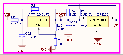
Perhaps you have to replace the resistor R62 to get the 5V supply properly....
regards
stancecoke
Thanks again for your help on this I have managed to follow the steps on the web doc using an st2 link and a s06s controller but this is the message I receive. I'm wondering if you have any further help to offer. Many Thanks in advance.
Configuration:
BoardName=ST-LINK ST-LINK_ID=0 Device=STM8S105x6 Port=USB ProgMode=SWIM
>>> Filling PROGRAM MEMORY image in computer with Blank Value
<<< Filling PROGRAM MEMORY image in computer succeeds
>>> Loading file main.hex in PROGRAM MEMORY image in computer
<<< Loading file succeeds
Hit 'Esc' key to abort during communication.
>>> Programming PROGRAM MEMORY
(API) ERROR : The device is protected
(API) WARNING : Operation aborted
<<< Programming PROGRAM MEMORY fails
stancecoke
1 MW
You have to press the "Write Option Bytes" Button of the Java Tool once with a brand new controller...
regards
stancecoke
regards
stancecoke
casainho
10 GW
- Joined
- Feb 14, 2011
- Messages
- 6,058
Maybe that button can have a more easy to understand name.stancecoke said:You have to press the "Write Option Bytes" Button of the Java Tool once with a brand new controller...
On TSDZ2 firmware, just recently I implemented a check at firmware startup that verifies the Option Bytes and if not as needed the firmware programs what is needed - this case, to enbale PMW N channels, since I remember the same for KT. This way the user just need to erase/unlock and flash, no need anymore to flash the option bytes.
Stancecoke I suggest you to copy my code.
nieles
10 kW
casainho said:Maybe that button can have a more easy to understand name.stancecoke said:You have to press the "Write Option Bytes" Button of the Java Tool once with a brand new controller...
On TSDZ2 firmware, just recently I implemented a check at firmware startup that verifies the Option Bytes and if not as needed the firmware programs what is needed - this case, to enbale PMW N channels, since I remember the same for KT. This way the user just need to erase/unlock and flash, no need anymore to flash the option bytes.
Stancecoke I suggest you to copy my code.
it isn't that easy for the KT controllers as they come with locked firmware. you need to do the write option bytes to erase the MCU.
casainho
10 GW
- Joined
- Feb 14, 2011
- Messages
- 6,058
Ok, I remember now. Also KT-LDC3 has protected firmware. I think TSDZ2 is not protected because is a way for the OEMs to be able to make some customization/configuration by writing on EEPROM, just like we could do on our firmwares. I am working to make more and more options configurable on LCD3 and they are stored on EEPROM.nieles said:casainho said:Maybe that button can have a more easy to understand name.stancecoke said:You have to press the "Write Option Bytes" Button of the Java Tool once with a brand new controller...
On TSDZ2 firmware, just recently I implemented a check at firmware startup that verifies the Option Bytes and if not as needed the firmware programs what is needed - this case, to enbale PMW N channels, since I remember the same for KT. This way the user just need to erase/unlock and flash, no need anymore to flash the option bytes.
Stancecoke I suggest you to copy my code.
it isn't that easy for the KT controllers as they come with locked firmware. you need to do the write option bytes to erase the MCU.
stancecoke
1 MW
casainho said:Maybe that button can have a more easy to understand name.
The name exactly describes what the button does The write protection is just one bit of the option bytes. The write protection is disabled and the PWM settings are adjusted with the same click. I think it can't be easier for the user.
It would help a lot, if new users would read the tutorial
regards
stancecoke
casainho
10 GW
- Joined
- Feb 14, 2011
- Messages
- 6,058
I can't blame others when I do the same as user, do something fast and see if works and if not, then I will use more time to read and understand why - if works at first, betterstancecoke said:casainho said:Maybe that button can have a more easy to understand name.
The write protection is just one bit of the option bytes. The write protection is disabled and the PWM settings are adjusted with the same click. I think it can't be easier for the user.
It would help a lot, if new users would read the tutorial
...
I think there is no issue for having only 1 button, that does always the same: flash option bytes + firmware.
Similar threads
- Replies
- 129
- Views
- 47,530
- Replies
- 2
- Views
- 3,635