stancecoke
1 MW
casainho said:I think there is no issue for having only 1 button, that does always the same: flash option bytes + firmware.
OK, that would be even easier
regards
stancecoke
casainho said:I think there is no issue for having only 1 button, that does always the same: flash option bytes + firmware.
stancecoke said:You have to press the "Write Option Bytes" Button of the Java Tool once with a brand new controller...
regards
stancecoke
stancecoke said:I'm still wondering, why the restarts don't happen, if the option DISPLAY_TYPE_KT_LCD3 is activated. (even in parallel to the option DIAGNOSTICS)
I just found and fixed a bug in the firmware. The UART-interrupt-routine was not declared, if no display was selected. Now it works without the pullup resistor at the rx-line in diagnostics mode.
geofft said:I did a calibration of the wattmeter recently and found that my motor has actually been drawing a max in excess of 1kw.
I think you can use in series my approach with your approach, if it brings value.stancecoke said:geofft said:I did a calibration of the wattmeter recently and found that my motor has actually been drawing a max in excess of 1kw.
Sorry, we can't improwe that, as we use the filtered battery current signal and do the current control in the slow loop. For this specific issue the implementation of casainho is better, as he uses the unfiltered battery current signal and reduces the duty cycle in the fast loop if over current is detected...
stancecoke said:geofft said:I did a calibration of the wattmeter recently and found that my motor has actually been drawing a max in excess of 1kw.
Sorry, we can't improwe that, as we use the filtered battery current signal and do the current control in the slow loop. For this specific issue the implementation of casainho is better, as he uses the unfiltered battery current signal and reduces the duty cycle in the fast loop if over current is detected...
We would need a high speed logger or an oszilloscope on the shunt to see, how long these peaks are, until the control-loop reduces the duty cycle... But I'm quite sure, those high currents will only appear, if you accelerate the motor from standstill with the throttle...
regards
stancecoke

stancecoke said:You have to press the "Write Option Bytes" Button of the Java Tool once with a brand new controller...
regards
stancecoke
You have to set the right number of serial cells in C#ROME-B for the correct bar displayreset said:Thanks again for your help on this but I'm struggling a little with the voltage reading on the display the LCD 3 displays battery but with 0 bars
you have to set the right value for undervoltage limitreset said:but will not respond to PAS or throttle input
stancecoke said:Thank you for the photos! So there seem to be two big resistors in parallel on your board. Sadly, I can't identify the colours of the resistor bands. Can you tell us the colours (or directly the resitance)?
regards
stancecoke

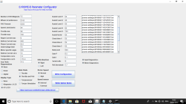
Hi this is the screen shot of the settings I'm using a q100 hub so I used that template as a starting point. I've managed to get the battery displaying the voltage by setting the controller C5 set to 0 so it tracks the incoming voltage. I've taken the throttle out of the equation as I can't seem to get that to work with the other controller(standard in changed). I also have the write config as a text file if that helps. Many Thanks againstancecoke said:You have to set the right number of serial cells in C#ROME-B for the correct bar displayreset said:Thanks again for your help on this but I'm struggling a little with the voltage reading on the display the LCD 3 displays battery but with 0 bars
you have to set the right value for undervoltage limitreset said:but will not respond to PAS or throttle input
If you have questions, please always post your config.h, otherwise we can't see what you are doing ....
regards
stancecoke


reset said:Hi this is the screen shot of the settings I'm using a q100 hub so I used that template as a starting point.
Hi this is the screen shot of the settings I'm using a q100 hub so I used that template as a starting point. I've managed to get the battery displaying the voltage by setting the controller C5 set to 0 so it tracks the incoming voltage. I've taken the throttle out of the equation as I can't seem to get that to work with the other controller(standard in changed). I also have the write config as a text file if that helps. Many Thanks again
reset said:snip.......
C:\Users\controller\Downloads\BMSBattery_S_controllers_firmware-Master\BMSBattery_S_controllers_firmware-Master>sdcc --version
SDCC : mcs51/z80/z180/r2k/r3ka/gbz80/tlcs90/ds390/pic16/pic14/TININative/ds400/hc08/s08/stm8 3.6.0 #9615 (MINGW64)
published under GNU General Public License (GPL)
........snip
I was hoping to use this controller with an 5s battery so it sounds like its not going to be possible.
reset said:Thanks for the input folks. I was hoping to use this controller with an 5s battery so it sounds like its not going to be possible.
reset said:I was hoping to use this controller with an 5s battery
stancecoke said:reset said:I was hoping to use this controller with an 5s battery
I just checked it on my testbench: the 48V! motor runs until a voltage of 15.5V with the origin R62 resistor. If I power the processor with the 5V supply from the STLink, it even runs down to 7.5V!
So no problem for our firmware :wink:
regards
stancecoke
