KT motor controllers -- Flexible OpenSource firmware for BMSBattery S/Kunteng KT motor controllers (0.25kW up to 5kW)

szkuba said:
From the other side i heard some poeple remove the excessive (five) speed magnets from the motor and then it works.

Are you crazy? :shock:

You just have to add a "*6" to one line of code!

ACAcommons.c line 98:
Code:
ui32_speed_sensor_rpks_accumulated += (((uint32_t)ui16_pwm_cycles_second)*1000) / ((uint32_t) (ui16_time_ticks_between_speed_interrupt*6));

regards
stancecoke
 
stancecoke said:
szkuba said:
From the other side i heard some poeple remove the excessive (five) speed magnets from the motor and then it works.

Are you crazy? :shock:

You just have to add a "*6" to one line of code!

ACAcommons.c line 98:
Code:
ui32_speed_sensor_rpks_accumulated += (((uint32_t)ui16_pwm_cycles_second)*1000) / ((uint32_t) (ui16_time_ticks_between_speed_interrupt*6));

regards
stancecoke
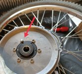
Not really crazy :wink: to me it is hardware mod. Looking at the MXUS 01C motor we can ser one magnet there but also space for additional 5. Thanks for your reply for now i do not feel confident to modify the code, although would like to learn more in future as this firmware works really great.
 

Attachments

  • IMG_20210115_074312.jpg
    IMG_20210115_074312.jpg
    153.3 KB · Views: 1,004
szkuba said:
to me it is hardware mod
Of course it works to remove the additional 5 magnets, but it takes at least 2h to disassemble the motor, remove the magnets and reassemble the motor. It only takes 2s to type "*6" :lol:

regards
stancecoke
 
stancecoke said:
Of course it works to remove the additional 5 magnets, but it takes at least 2h to disassemble the motor, remove the magnets and reassemble the motor. It only takes 2s to type "*6" :lol:

regards
stancecoke
Then it is really faster, although i do not know where is the main code :oops:
 
Hello

I am using the erider torque sensor om my bike.

I recently changed the wiring of it so that it is now conmected in this way

https://ibb.co/Y8gxnc6

After this I blew the power supply for the torque sensor, replaced it and blew it again. Can anyone see something obviously stupid I have done?

The power supply is one of these

https://a.aliexpress.com/_mOOiyBf
 
I am trying to use this firmware for a project, where I only use the thumb drive input. Unfortunately, my incoming signal is rather noisy. (I smoothed it already with filtering & averaging, Still noisy.)

But while I get good motor control results with the std. firmware, this opensource firmware results in erratic / non smooth Motor behavior (under load).

Therefor my questions:
- Does someone have a recommendation for Gain P an Gain I settings, which makes the thumbdrive behavoir as close as possible to stock performance?
(right now, I am at values around 1 for both parameters; when I go down to i.e. 0.2 the system does not react at all anymore on the throttle input, which I find odd as that are the default settings. Can this be triggered by too fast throttle input changes?)

- Can someone explain in more words than the wiki(*) how these 2 parameters impact throttle behavior?

(*) GAIN P: Proportional factor of the PI controller. The higher the value is selected, the higher the risk, that the control starts oscillating.
GAIN I: Integral factor of the PI controller. The smaller the value, the smoother the control runs into the setpoint. Both gain values must be written with a dot as a decimal separator.
 
endlessolli said:
this opensource firmware results in erratic / non smooth Motor behavior (under load).

What is your setting for max battery current and for max phase current?
Set max phase current much higher than max battery current!

regards
stancecoke
 
stancecoke said:
endlessolli said:
this opensource firmware results in erratic / non smooth Motor behavior (under load).

What is your setting for max battery current and for max phase current?
Set max phase current much higher than max battery current!

regards
stancecoke

Thanks for the reply, stancecoke!
These are my current settings:
Battery current = 70
Phase current = 100
Cal a = 50 (I have small a 6 FET controller - so I should put this to 100 accroding to the wiki. (Is that a fudge factor or is there a way to calculate the correct value?)

I also found another potential issue: I digged some more in the forums (also german pedelec forum) and realized that my 'pre-controllers' RC low pass filter for the thumb input was maybe too low. (You used 1kOhm & 5µF for some experiments, the 'Forum-controller' uses 150Ohm and 100µF; I used 10kOhm & 5µF. Still wondering why it worked w/ the std. Firmware and not so good with your open source f/w.
I will also experiment with the current settings.
But the weather forces me to take a break......
 
Hello. I suppose I ordered the so called "high level" brake sensor for my s06s controller, which has 3 wires instead of 2.https://bmsbattery.com/parts/459-hwbs-hidden-wire-brake-sensor-1pcs-parts.html The Blueterm shows the following when I activate the brake:

Code:
4350,0, 0, 325, 0, 0
4350,0, 0, 325, 0, 0
4350,0, 0, 325, 0, 0
4350,0, 0, 325, 0, 0
1,0, 0, 324, 0, 0
1,0, 0, 325, 0, 0
1,0, 0, 325, 0, 0
1,0, 0, 324, 0, 0
1,0, 0, 324, 0, 0
1,0, 0, 325, 0, 0
1,0, 0, 325, 0, 0
1,0, 0, 325, 0, 0
1,0, 0, 324, 0, 0
1,0, 0, 324, 0, 0
1,0, 0, 325, 0, 0
1,0, 0, 325, 0, 0
1,0, 0, 324, 0, 0
1,0, 0, 325, 0, 0
1,0, 0, 325, 0, 0
4350,0, 0, 325, 0, 0
4350,0, 0, 324, 0, 0
4350,0, 0, 325, 0, 0
4350,0, 0, 324, 0, 0
4350,0, 0, 325, 0, 0

If I'm correct the brake is ON at default and prevents any operation whatsoever. My question is, can I use these with my s06s controller at all or do I need to buy the "low level" ones? Maybe modify these to make them work with my controller?
 
stancecoke said:
Slipy said:
motor spin all time at very low speed

Nice to see the motor spinning, this is a great sucess already! Congratulations!

It seems that the battery-current measuring is not stable fast enough at startup. We already have build in a pause in the autozero procedure in the adc_init(void) function, but it seems to be too short.
You can try to increase the number of loop runs in the delay-loop, or just use a higher offset (e.g. 5 instead of 1) in line 79 of the adc.c

Code:
ui16_current_cal_b -= 1;

regards
stancecoke
I had similar problem with wheel spining after running the motor and tried to modify the code. It worked well with offset "3"
 
I wanted to share two small e-bike conversion with Open Firmware recently acomplished to my family and friends:
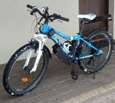
1. 24inch e-MTB with Q85 motor, and Sempu T4 IMG_20210109_183319.jpg
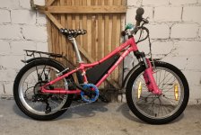
2. 20inch with bafang 020.350 DC and eRider T9 IMG20210123181227-1.jpg
Both have reduced battery current to 7A and Phase current to 20A, also to accomodate smaller rider size the cranks are 152mm instead of 170mm
Basically i use stock perimeterers from custom software besides TQ calibration lowered to "1000" to accomadate lower mass of entire setup - rider plus bike :)
my fellings are:
1. that firmware on Sempu T4 does react faster - due to more PAS magnets perhaps :roll: . But the sensor feels like cutting of randomly
2. eRider T9 setup reacts slower but is more stable.
3. Both are very gentle and can safely be used by kids - under adult supervision of course

Thanks to all who contribute to this great software. We can now democratise e-biking among the kids as well :D
 
stancecoke said:
Valopallo said:
This is the effect of the throttle.
Very good! So nothing's wrong with the controller :)
We have to check the hallsensor-signals next.

Put in GPIO_ReadInputData(HALL_SENSORS__PORT) & (HALL_SENSORS_MASK) instead of ui16_setpoint now. Then turn the motor shaft slowly by hand. The signal sequence has to be 4-6-2-3-1-5. If you have to turn the motor backwards due to a freewheel, the order is vice versa of course. If the sequence is OK, you have to find the right motor specific angle.
The meaning of the first value (ui16_control_state) can be decrypted as described here.

regards
stancecoke

I was in this situation a year ago with another controller and HALL sensors. I managed to fry them and now I'm attempting to build back my system once again. This time the problem seems to be at the HALL sensors, even though I used these same sensors(same lot) to my rear motor without any problems whatsoever. This is the same smaller geared hub at the front wheel as year ago. New sensors though.

When I add this line to the main.c
Code:
GPIO_ReadInputData(HALL_SENSORS__PORT) & (HALL_SENSORS_MASK)
and read the controller data with Blueterm it gives me this:

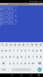
Screenshot_20210124-215835.png

After 10 seconds the controller stops sending any info. Turning the wheel does not give any HALL sensor sequence reading. Also the output voltage of the sensors switch from 5V to -5V(between Vin and HALL signals) and 0 to 8V(between GND and HALL signals) measured with a multimeter. What's happening here? There are no pull up resistors or capacitors installed because I have never needed them with these motors and controllers. Could the pull up resistor help with this?
Without HALL sensors plugged in, the Blueterm seems to read data as it should.

How to troubleshoot?
 
Valopallo said:
How to troubleshoot?
The system reboots all the time.
I guess this is a problem with the 5V supply of the controller. Disconnect one external device after the other (Throttle, PAS, Motorhalls ...) from the 5V rail and see, if the controller still freezes.
Do you have an extra DC/DC converter for the BT module?

Other possibility is that the watchdog resets the processor. But no idea why...

regards
stancecoke
 
stancecoke said:
Valopallo said:
How to troubleshoot?
The system reboots all the time.
I guess this is a problem with the 5V supply of the controller. Disconnect one external device after the other (Throttle, PAS, Motorhalls ...) from the 5V rail and see, if the controller still freezes.
Do you have an extra DC/DC converter for the BT module?

Other possibility is that the watchdog resets the processor. But no idea why...

regards
stancecoke

Yes, I have done that and the rebooting happens only with the HALL sensors plugged in. But, do you think that those voltage values of the HALL sensor I mentioned are an indication of a faulty HALL sensor behavior or do they seem normal? They do switch clearly, but the voltages are not +5V and 0V. Is it even relevant? I tested those values with external 5V PSU so it's not related to the controller 5V rail.

EDIT: Nevermind. It seems these shitty HALL sensors somehow blew the whole 2WD system. 5V rail dropped to 2.6V at both controllers and that includes PAS, Throttle, Brakes and HALLs which are not connected when measuring. Blueterm does not read anything anymore, even though it did just yesterday. The rear motor actually worked like it should with PAS the other night. Any hope left?
 
Valopallo said:
Any hope left?

If the voltage returns to 4.3V after disconnection the motor halls, the controllers should be OK at least.

You can check if the hall cables are weared somewhere and cause contact to the bike frame e.g. But it's quite easy to replace the hallsensors and the cables. Of course you have to open the motor for repair.

regards
stancecoke
 
stancecoke said:
Valopallo said:
Any hope left?

If the voltage returns to 4.3V after disconnection the motor halls, the controllers should be OK at least.

You can check if the hall cables are weared somewhere and cause contact to the bike frame e.g. But it's quite easy to replace the hallsensors and the cables. Of course you have to open the motor for repair.

regards
stancecoke

No hope. The HALL sensors were bad and also the motor harness had one signal wire cut. More money to china! "Build your own, it's going to be cheaper", they said. :confused:
 
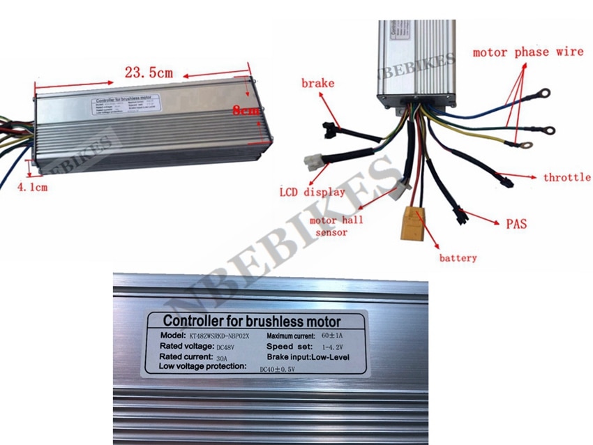
Hello, I plan to buy a KT 60V 60A but the label on the controller says "KT60ZWSRK....". From my understanding ZW stands for square wave.

If I upload a new FW with the tool, will it run sine wave simplified FOC?

An other question : is it possible to run at 64v (16s battery) without any mods a KT labeled as 48V dc; this one for instance :
Hcfed6c4b915d4ad19482a0eaddc9b282j.jpg


cheers
 
After carefully read the Wiki, ZW cannot be turned to Sinewave by Software. Is there a way to mod the controller in order to activate interpolation?

Second question : Is there a way to dump the original FW of the controller, the "factory" firmware. I have a STLINK.

Thanks
 
atkforever said:
ZW cannot be turned to Sinewave by Software. Is there a way to mod the controller in order to activate interpolation?

you can use sinusoidal commutation, if you have Motorhallsensors. You can't use the "simplified" FOC. To use it, you have to solder the ACS phase current sensor to the PCB and remove the solder bridge.

atkforever said:
Is there a way to dump the original FW of the controller, the "factory" firmware. I have a STLINK.

no.

regards
stancecoke
 
stancecoke said:
atkforever said:
ZW cannot be turned to Sinewave by Software. Is there a way to mod the controller in order to activate interpolation?

you can use sinusoidal commutation, if you have Motorhallsensors. You can't use the "simplified" FOC. To use it, you have to solder the ACS phase current sensor to the PCB and remove the solder bridge.

atkforever said:
Is there a way to dump the original FW of the controller, the "factory" firmware. I have a STLINK.

no.

regards
stancecoke

What are the pros and the cons of using FOC rather than sinusoidal commutation ?
 
atkforever said:
pros and the cons of using FOC rather than sinusoidal commutation ?

The efficiency at high load an high speed is better with FOC. Less heat and more torque

regards
stancecoke
 
I understand the theoretical reasons the FOC control is better, but has anyone actually run a bike with a DD hub motor with this open source firmware and also run same bike with standard KT controller to see real world results ? Like Watt hrs/ km and top speed results ?
I use KT controller that was 9 fet but now 6 fet ( pulled cheap fets that were doubled up and replaced with K150E09NE so all the same ).
Can this tool chain run under linux ? Or maybe Windows 7 in VM ?
Thanks
 
How can I get my SVP controller to work in sinewave mode? I can see all sorts of wavetables in the wavetables folder and the motor sounds as if it is being driven by a standard squarewave controller.
 
hi all

this is my first post on this site so sorry in advance for any mistakes

i bought a kt controller from lightingbike on aliexpress i believe its the 18 mosfet Bluetooth but i think i went for dual mode thinking it meant that it could do regen brakes i think its called

i think i may have ended up with mod sine instead of sinewave as a result and dual mode may mean something about with and without hall sensors

can anyone tell me if this is correct

i bought it to upgrade my voilamart 1500w controller as i hoped for the braking and to be able to run at high volts but reduce amps

everything works, bluetooth connects but no data displays on KT bluetooth app, i was told i dont need a display i have some jumper leads that came on controller

i would like to try this software soon but not even sure if i have a problem first with motor, controller and/or combination

hall sensors plug matched and all worked straight away

would like to be able to see volts and amps on KT app they sent me, can anyone help

side note i plan to when i understand what to do beter upgrade to this open source software but would like to try this first and dont have any funds to invest in this just yet am still saving for a BMS

also while i see members on here saying sinewave is best is it possible to use the modified sine version with this software and not get some features or reduced performance

sorry if these questions have been asked or im asking wrong or in wrong place, i honestly have looked and use google and am probably over 500 hours into my first ebike build having amazing fun and am hoping to maybe post my build

thanks in advance to all
 
Back
Top