
You are using an out of date browser. It may not display this or other websites correctly.
You should upgrade or use an alternative browser.
You should upgrade or use an alternative browser.
KT motor controllers -- Flexible OpenSource firmware for BMSBattery S/Kunteng KT motor controllers (0.25kW up to 5kW)
- Thread starter casainho
- Start date
casainho
10 GW
- Joined
- Feb 14, 2011
- Messages
- 6,058
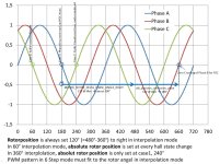
Sorry, I almost don't have time to analyze all the information you wrote.stancecoke said:In the video the motor starts in 6 steps, with reaching 200 erps it switches to 60° interpolation and immediatly falls back to 6 step, but the shown erps are suddenly lower than before, but you don't recognize the Chainwheel is turning slower ?!
For the video, I would say 6 steps are working well!! The issue is the transition... you may remember that I had big problems with one motor!! For what I see, the transition is failing and the solution may be:
- change the erps value at which the transition happen (forget the 360º for now, focus only on 60º sinewave)
- change the initial angle for the sinewave: you may start by disabling "FOC" because it may be giving problems... FOC must be needed over big changes on speed, so just to test the transition, FOC can be disabled.
After you get your motor working, we need to learn with this process for future different motors!!
stancecoke
1 MW
I think you have looked at phase B current with you oszilloscope. Is it the falling edge or the rising edge when we do the FOC?
regards
stancecoke
regards
stancecoke
casainho
10 GW
- Joined
- Feb 14, 2011
- Messages
- 6,058
I don't remember but if is not one signal, is the inverse. If you log the angle correction value, yoi will going in one or other direction, the direction that works will stabilize tje value and will work.stancecoke said:I think you have looked at phase B current with you oszilloscope. Is it the falling edge or the rising edge when we do the FOC?
casainho
10 GW
- Joined
- Feb 14, 2011
- Messages
- 6,058
If you think FOC is not working correctly and is causing problems: the evaluation is on case 3:casainho said:I don't remember but if is not one signal, is the inverse. If you log the angle correction value, yoi will going in one or other direction, the direction that works will stabilize tje value and will work.stancecoke said:I think you have looked at phase B current with you oszilloscope. Is it the falling edge or the rising edge when we do the FOC?
Code:
if (ui8_ADC_id_current > 127)But maybe it is different on your motor and you may need to test to put it at any of the 6 steps.
Alan B
100 GW
I was thinking about this from a programming perspective, instead of the wiring perspective we usually use to make a controller work.
We have a three phase input (halls) and a three phase output (motor wires). Taken individually, each of these has exactly two unique configurations, corresponding to the two directions of rotation. Swapping any two signals produces the other rotational direction.
Taken together we have three "rotations", corresponding to 0, 120 and 240 degrees.
Collectively this makes 12 combinations.
In the software we must provide for these 12 possible situations, but it can be covered with three "switches" that each control one of the variables.
That about covers it.
casainho
10 GW
- Joined
- Feb 14, 2011
- Messages
- 6,058
I will need to think on this. I must say I am not motivated to do it now... and I remember all the time it took me to find the correct sequenceAlan B said:I was thinking about this from a programming perspective, instead of the wiring perspective we usually use to make a controller work.
We have a three phase input (halls) and a three phase output (motor wires). Taken individually, each of these has exactly two unique configurations, corresponding to the two directions of rotation. Swapping any two signals produces the other rotational direction.
Taken together we have three "rotations", corresponding to 0, 120 and 240 degrees.
Collectively this makes 12 combinations.
In the software we must provide for these 12 possible situations, but it can be covered with three "switches" that each control one of the variables.
That about covers it.
")
casainho
10 GW
- Joined
- Feb 14, 2011
- Messages
- 6,058
I implemented the MOTOR_OVER_SPEED_ERPS protection. The motor speed controller limits the motor speed to MOTOR_OVER_SPEED_ERPS -- this limits superimposes to the speed value set by user using void motor_speed_controller_set_erps (uint16_t erps);, for instance:
- I defined:
And now my motor gives only max speed of 27.7km/h instead of the 45km/h as before. This parameter is important to protect the controller, to avoid to much heat and current spikes - but this is a guess, needs to be validated.
The changes to the motor_speed_controler code:
And the final code:
- I defined:
Code:
#define MOTOR_OVER_SPEED_ERPS 390 // motor max speed, protection max value | 40 points for the sinewave at max speedThe changes to the motor_speed_controler code:
Code:
  ui16_motor_speed_erps = motor_get_motor_speed_erps ();

  // if MOTOR_OVER_SPEED_ERPS, then limit for this value and not user defined target_erps
  if (target_erps > MOTOR_OVER_SPEED_ERPS)
  {
    i16_error = MOTOR_OVER_SPEED_ERPS - ((int16_t) ui16_motor_speed_erps);
  }
  else
  {
    i16_error = target_erps - ((int16_t) ui16_motor_speed_erps);
  }
And the final code:
Code:
#define MOTOR_OVER_SPEED_ERPS 390 // motor max speed, protection max value | 40 points for the sinewave at max speed
#define MOTOR_SPEED_CONTROLLER_KP 5 // x << 5
#define MOTOR_SPEED_CONTROLLER_KI 2 // x << 5
#define MOTOR_SPEED_CONTROLLER_OUTPUT_MAX 8000 // PWM max duty_cycle << 5

uint16_t target_erps = 0;

void motor_speed_controller_set_erps (uint16_t erps)
{
  target_erps = erps;
}

// call every 100ms
void motor_speed_controller (void)
{
  int16_t i16_error;
  int16_t i16_p_term;
  static int16_t i16_i_term;
  int16_t i16_output;
  uint16_t ui16_motor_speed_erps;

  ui16_motor_speed_erps = motor_get_motor_speed_erps ();

  // if MOTOR_OVER_SPEED_ERPS, then limit for this value and not user defined target_erps
  if (target_erps > MOTOR_OVER_SPEED_ERPS)
  {
    i16_error = MOTOR_OVER_SPEED_ERPS - ((int16_t) ui16_motor_speed_erps);
  }
  else
  {
    i16_error = target_erps - ((int16_t) ui16_motor_speed_erps);
  }

  i16_p_term = i16_error * MOTOR_SPEED_CONTROLLER_KP;
  i16_i_term += i16_error * MOTOR_SPEED_CONTROLLER_KI;
  // windup control
  if (i16_i_term > MOTOR_SPEED_CONTROLLER_OUTPUT_MAX) i16_i_term = MOTOR_SPEED_CONTROLLER_OUTPUT_MAX;
  else if (i16_i_term < 1) i16_i_term = 0;
  if (target_erps < 3) i16_i_term = 0; // avoid I term errors when target_erps = 0

  i16_output = i16_p_term + i16_i_term;
  // limit max output value
  if (i16_output > MOTOR_SPEED_CONTROLLER_OUTPUT_MAX) i16_output = MOTOR_SPEED_CONTROLLER_OUTPUT_MAX;
  else if (i16_output < 1) i16_output = 0;
  i16_output >>= 5; // divide to 32, as MOTOR_SPEED_CONTROLLER_KP and MOTOR_SPEED_CONTROLLER_KI are 32x; avoid using floats

  motor_set_pwm_duty_cycle_target ((uint8_t) i16_output);
}Alan B
100 GW
Making it easy for others to configure for their motors and wiring will be more important as time goes forward, otherwise new users will need too much help or some will give up.
casainho
10 GW
- Joined
- Feb 14, 2011
- Messages
- 6,058
stancecoke,
I updated the motor branch with my latest code.
I updated the motor branch with my latest code.
Yes, I understand. That is also why stancecoke implemented the PC java software for setup the firmware options.Alan B said:Making it easy for others to configure for their motors and wiring will be more important as time goes forward, otherwise new users will need too much help or some will give up.
stancecoke
1 MW
I've tried to get the information, if there's a falling or rising edge at case3, where we do the FOC. Therefore i read in the PhaseB current at case2 (120°), case 3 (180°) and case1 (240°).
The result at ramping up speed with a little load is intersting:
first start: falling edge (135, 128, 123)
after jerk in 6 step mode: maximum at case 3 (130,132,126)
in interpolation mode: rising edge (126, 127, 128) (that fits to my sketch from post #600 but the current +/- 60 degree away from case3 seem to be much to small ?!
The "self-learning" procedure of some chinese controllers is well documentated here:
http://www.etotheipiplusone.net/?p=2373
edit: there is something wrong with adc conversion obviously. The read Motor current total is runnig from 0 to max all the time and FOC is not working as Phase B current stays at 127 -/+ 1 all the time in interpolation mode..
I checked it with my old code, there is everything OK, so no hardware defect...
I'm not able to compile your SVM7, I don't now why....
I'll now spend the afternoon with enjoying the "indian summer" in Munich ! 8)
regards
stancecoke
Regards
stancecoke
The result at ramping up speed with a little load is intersting:
first start: falling edge (135, 128, 123)
after jerk in 6 step mode: maximum at case 3 (130,132,126)
in interpolation mode: rising edge (126, 127, 128) (that fits to my sketch from post #600 but the current +/- 60 degree away from case3 seem to be much to small ?!
The "self-learning" procedure of some chinese controllers is well documentated here:
http://www.etotheipiplusone.net/?p=2373
edit: there is something wrong with adc conversion obviously. The read Motor current total is runnig from 0 to max all the time and FOC is not working as Phase B current stays at 127 -/+ 1 all the time in interpolation mode..
I checked it with my old code, there is everything OK, so no hardware defect...
I'm not able to compile your SVM7, I don't now why....
Code:
make: *** No rule to make target `StdPeriphLib/src/stm8s_itc.rel', needed by `main'. Stop.I'll now spend the afternoon with enjoying the "indian summer" in Munich ! 8)
regards
stancecoke
Regards
stancecoke
casainho
10 GW
- Joined
- Feb 14, 2011
- Messages
- 6,058
Thanks for the self learning link, I already went over that message blog but didn't save that info and that is right what I wanted to find -- just saved on notes file, later will put online.stancecoke said:I've tried to get the information, if there's a falling or rising edge at case3, where we do the FOC. Therefore i read in the PhaseB current at case2 (120°), case 3 (180°) and case1 (240°).
The result at ramping up speed with a little load is intersting:
first start: falling edge (135, 128, 123)
after jerk in 6 step mode: maximum at case 3 (130,132,126)
in interpolation mode: rising edge (126, 127, 128) (that fits to my sketch from post #600 but the current +/- 60 degree away from case3 seem to be much to small ?!
The "self-learning" procedure of some chinese controllers is well documentated here:
http://www.etotheipiplusone.net/?p=2373
edit: there is something wrong with adc conversion obviously. The read Motor current total is runnig from 0 to max all the time and FOC is not working as Phase B current stays at 127 -/+ 1 all the time in interpolation mode..
I checked it with my old code, there is everything OK, so no hardware defect...
I'm not able to compile your SVM7, I don't now why....
Code:make: *** No rule to make target `StdPeriphLib/src/stm8s_itc.rel', needed by `main'. Stop.
I'll now spend the afternoon with enjoying the "indian summer" in Munich ! 8)
That issue on building, I think you need to first "make -f Makefile_linux clean" than that error should disappear.
Try printf the values while the motor is stopped. Phase B current should be 127, etc. For me, the ADC is working ok (throttle, phase B current, motor current and battery voltage).
Would be great if you could find and alternative to serialplot to your Windows!! That way you could debug way faster!!
So, can you please tell if with FOC disable, the transition to sinewave works ok or not?? I must say I don't know where do you stay. What I could understand is that 6 steps is working ok and that maybe you found FOC is not working for you (but I think FOC were working before for you).
You can checkout my motor branch and test directly with a throttle -- you will need to make the changes for your motor. It should work, at least is working for me since a few commits ago.
casainho
10 GW
- Joined
- Feb 14, 2011
- Messages
- 6,058
Firmware strucute
Stancecoke,
Looking at your update_setpoint(), you are doing:
- battery voltage max and min protection
- speed controller
- Throttle | PAS | Torque sensor
I did implement the speed controller on the motor layer. I also want now to implement battery voltage max and min protection as I think they belong to the motor controller but to high level layer and so at the higher level layer of motor controller:
- variables like speed in km/h, etc, needed to be used by communications
- battery voltage max and min protection
- speed controller
Then on top, we can put the Throttle | PAS | Torque sensor controller. I hope it is ok for you. This seems to be more modular and easy to understand/maintain/hack. I will keep looking at your code while implementing this.
stancecoke
1 MW
I've now tested your SVM 7 branch, it's the same as in my merged branch, ADC not working properly and start up is sticky....
Perhaps you can upload an .hex file of your running code (with printing out the adc values) to test, if it's a matter of compiling perhaps....
regards
stancecoke
Perhaps you can upload an .hex file of your running code (with printing out the adc values) to test, if it's a matter of compiling perhaps....
regards
stancecoke
casainho
10 GW
- Joined
- Feb 14, 2011
- Messages
- 6,058
Get test_ADC branch (main.bin and main.elf files). On main:stancecoke said:I've now tested your SVM 7 branch, it's the same as in my merged branch, ADC not working properly and start up is sticky....
Perhaps you can upload an .hex file of your running code (with printing out the adc values) to test, if it's a matter of compiling perhaps....
Code:
printf("%d, %d, %d, %d\n", ui8_adc_read_phase_B_current (), ui8_adc_read_throttle (), ui8_adc_read_motor_total_current (), ui8_adc_read_battery_voltage ());The output:

stancecoke
1 MW
can you please upload the .ihx file. The windows based bin2hex leads to a main.hex that is 46kB big. I think that can't work.
And please activate the PWM, otherwise I can't read the current....
Regards
stancecoke
And please activate the PWM, otherwise I can't read the current....
Regards
stancecoke
casainho
10 GW
- Joined
- Feb 14, 2011
- Messages
- 6,058
Ok I will. But that code shows the 4 currents and if it work like that, should also work with motor rotating.stancecoke said:can you please upload the .ihx file. The windows based bin2hex leads to a main.hex that is 46kB big. I think that can't work.
And please activate the PWM, otherwise I can't read the current....
casainho
10 GW
- Joined
- Feb 14, 2011
- Messages
- 6,058
Done. Added this line to my makefile to get the hex file:stancecoke said:can you please upload the .ihx file. The windows based bin2hex leads to a main.hex that is 46kB big. I think that can't work.
And please activate the PWM, otherwise I can't read the current....
Code:
$(OBJCOPY) -O ihex $(ELF_SECTIONS_TO_REMOVE) $(PNAME).elf $(PNAME).hex
stancecoke
1 MW
OK, in this branch, adc works OK. With your hex-file and with compiling it by myself. But the FOC is working in the wrong direction. If it switches to interpolation, the current runs away...
regards
stancecoke
regards
stancecoke
casainho
10 GW
- Joined
- Feb 14, 2011
- Messages
- 6,058
Invert the signals of increments/decrements of the angle correction value.stancecoke said:OK, in this branch, adc works OK. With your hex-file and with compiling it by myself. But the FOC is working in the wrong direction. If it switches to interpolation, the current runs away...
Maybe you can now wait for me to integrate on my branch the code for the motor controller high level. Then it will need the code you already did for throttle,pas,torque sensor + the LCD that you already did and is very modular, so should be easy to see my branch to became the stable branch -- not need for you to try work your branch.
casainho
10 GW
- Joined
- Feb 14, 2011
- Messages
- 6,058
I added motor_battery_voltage_protection();
Added a low pass filter, to avoid possible fast spikes/noise.
For now, when the max/min happens, the motor stops and systems hangs. For future I need to implement error flags and motor states, so the motor controller can then:
- when max voltage, regen should be disabled as I think it is the only way for the battery increase it's voltage
- when min voltage, I think motor should be disable for a few seconds like 20, before enable it again
Current code:
Code:
void motor_battery_voltage_protection (void)
{
  // low pass filter the voltage readed value, to avoid possible fast spikes/noise
  ui16_ADC_battery_voltage_accumulated -= ui16_ADC_battery_voltage_accumulated >> 4;
  ui16_ADC_battery_voltage_accumulated += ui8_adc_read_battery_voltage ();
  ui16_ADC_battery_voltage_filtered = ui16_ADC_battery_voltage_accumulated >> 4;

  if (ui16_ADC_battery_voltage_filtered > BATTERY_VOLTAGE_MAX_VALUE)
  {
    // TODO: disable motor regen

motor_set_mode_coast ();
while (1) ; // infinite loop, user will need to reset the system
  }
  else if (ui16_ADC_battery_voltage_filtered < BATTERY_VOLTAGE_MIN_VALUE)
  {
    // TODO: disable motor for 20 seconds and signal error

motor_set_mode_coast ();
while (1) ; // infinite loop, user will need to reset the system
  }
  else
  {
    // TODO: enable motor regen
  }
}Alan B
100 GW
One thing you could do, in both cases, is adjust the PWM to allow the voltage to be within spec, reduce on time in the low voltage case, or reduce regen in that case. Do the best that can be done, the rider might need to clear the intersection and cutting throttle might be a bad thing to do right at that moment.
Just something to think about.
When we built realtime systems we tried to make them do the best they could rather than just give up.
Just something to think about.
When we built realtime systems we tried to make them do the best they could rather than just give up.
casainho
10 GW
- Joined
- Feb 14, 2011
- Messages
- 6,058
Stancecoke,
See my clean main loop now. It just misses the communications controller, which I will start implementing next, for my Kunteng LCD (including your code for your LCD). We are now close to have a full working firmware -- but with a lot of things to improve, sure.
It follows the firmware structure I drew before:
See my clean main loop now. It just misses the communications controller, which I will start implementing next, for my Kunteng LCD (including your code for your LCD). We are now close to have a full working firmware
-- but with a lot of things to improve, sure.
Code:
  while (1)
  {
    ui16_TIM2_counter = TIM2_GetCounter ();
    if ((ui16_TIM2_counter - ui16_motor_controller_counter) > 100) // every 100ms
    {
      ui16_motor_controller_counter = ui16_TIM2_counter;
      motor_controller_high_level ();
      continue;
    }

    ui16_TIM2_counter = TIM2_GetCounter ();
    if ((ui16_TIM2_counter - ui16_throttle_pas_torque_sensor_controller_counter) > 20) // every 20ms
    {
      ui16_throttle_pas_torque_sensor_controller_counter = ui16_TIM2_counter;
      throttle_pas_torque_sensor_controller ();
      continue;
    }
}casainho
10 GW
- Joined
- Feb 14, 2011
- Messages
- 6,058
I understand what you mean. Also I think it will bring complexity which is something I want to avoid on this phase: now I just want to have a working firmware that will not be perfect but should have a good working base. Improvements can be done after.Alan B said:One thing you could do, in both cases, is adjust the PWM to allow the voltage to be within spec, reduce on time in the low voltage case, or reduce regen in that case. Do the best that can be done, the rider might need to clear the intersection and cutting throttle might be a bad thing to do right at that moment.
Just something to think about.
When we built realtime systems we tried to make them do the best they could rather than just give up.
For instance: my Smart electric car (Daimler AG), when the battery is fully charged and I leave the garage, I need to make about 4 kms before the regen/electric brake works other way just the mechanical brake works -- this is written on manual. I see no reason to do implement different from this, at least in the first version of the firmware.
For battery low voltage, again, my Smar electric car, shows a "fuel reserve" warning and it is up to me to take care with my driving on the stage. On Kunteng LCD, since I remember, the user also gets the same warning!
So to resume, I think we need to simplify.
stancecoke
1 MW
I'm sad, you have thrown away all my ifdefs for the different ride modes...casainho said:Stancecoke,
See my clean main loop now.
I will concentrate on the start up procedure for my motor with 6 steps now. (And perhaps I'll understand what is happening ...)
Regards
stancecoke
Similar threads
- Replies
- 129
- Views
- 45,764
- Replies
- 2
- Views
- 3,553