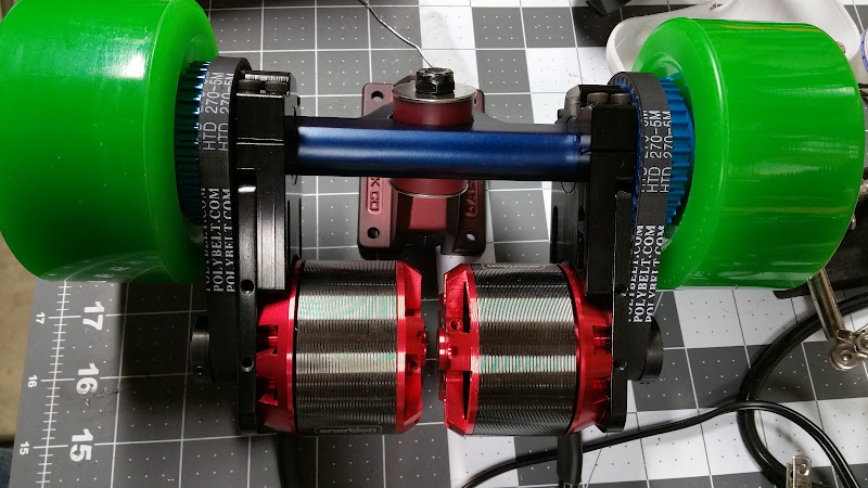
Landyachtz TopSpeed 90mm 10S4P DualRearDrive

dnmun said:
but there is no need to use solder wick. bare copper wire, called bus wire would work better and be 1/10 of the cost.

i am sorry you feel it is a 'downer' to try to inform people about the laws of physics and electrical conduction.

everyone feels most comfortable doing what someone else has done. fanboys feel they are doing the right thing if they follow the previous guys technique. that is more important to them than understanding the laws of physics.

like chaka correctly said - I just added 5mm^2 copper to the serial connections of 2 4P packs and copper wick was the only thing I had at hand. not sure why you kept making these remarks about laws of physics and electrical conduction, even after realising that you actually got it wrong. its sort of ironic too, cause im a physicist! :D also not sure whats the point argueing about 0.10eur vs 1eur for a few wires in a 1500€ project ... :) but ok, point taken, save 1-2euro per pack by not using copper wick, but bare copper wire instead!

I dont think I did anything wrong besides that --- in fact I gave my first and also this 2nd battery a lot of thought, from individual cell load and correct cell choice over current capabilities of the connections and most simple/robust building order. I really think its easiest if you start with parallel cell packs first, since the nickel band on top and botton will stabilise the individual packs nicely for further connections. also, that way you will have exactly 2 balancer cables per serial pack.

just out of curiosity - how would YOU build this 10S4P pack? would you rather wire 10 cells in serial and then connect them in parallel at the end with a giant mess of balancer cables? that doesnt sound very practical at all, also the 10cell serial packs wont be mechanically robust since youll alternate connections on top/bottom unlike the 4cell parallel packs. dont really get your criticism at all the more I think about it. :?

@chaka: hmm, I didnt really think about faulty cells - guess thats always annoying in a spot welded pack anyway. is that a common phenomenon in a large batterypack with comparably low load?
 
Faulty cells are probably a non issue since each cell has an internal fuse. I use fuse wires for the initial connection to gain a level of redundancy, I imagine the fuse wires would also save the cells in the event of a mechanical short due to damage/crash. My last point is probably the reason Tesla Motors uses fuse wires to connect their 18650 cells.
 
yes i recommend building a battery from paralleling serial packs. i find it is the only way to isolate a self discharging cell later in the life of the battery and i also feel that the individual paralleling links, the sense wire, be of small gauge wire capable only of handling the balancing current. it is as easy to build up a pack that way as to connect them in parallel first. but people connect them in parallel first all the time because that is all they ever see people do. just as the chinese do in their mass production facilities.

i also have explained how to solder the cans together using small copper links instead of spot welding. i also try to warn people of spot welding to the center of the bottom of the case to reduce the risk of damaging the central core and blocking the protective feature of the hollow core to venting or damaging the negative current collector where it is connected to the bottom of the can.

you can carry up to 40A in a small serial copper link of 4mm^2 cross section. so a small link, 20mm long, 1mm thick, and 4mm wide could carry up to 40A in serial links. i recommend soldering the link on the edge of the bottom, so the heat is captured by the wall of the can during reflow of the pretinned contact during soldering. i consider soldering to the anode to be less damaging and the anode button is physically and thermally separated from the current collector to reduce the risk of heating from soldering to the anode. but i recommend using the wet sponge immediately after reflow to terminate the case heating.

i would also be interested in what you do as a physicist. do you have work or have to teach school? would i be familiar with any project you were involved in? you indicated i was wrong but did not state why i was wrong or what i was wrong in observing. or instructing is how i view it.
 
ah, I dont really know much about the internals of these cells, so this was very interesting to read, thanks for taking the time. somehow I liked this post a lot more than the "fanboys, dont follow that guy, he doesnt even know basic physics" post of yours. :wink:

I was a little afraid of soldering to be honest, mostly because of the heat (nice tip with wet sponge, I used a wet cold towel after shrink wrapping to get the heat out quick :D ). I experimented a little with flux and different tip sizes on old cells and I felt like I might manage ... but at the same time nickel band gives nice structural support while building unlike copper wires --- and without the risk of potentially destroying a cell. So I ultimately build my 80$ spot welder and went for it. my first battery didnt have this massive expected current output, but for the new one I knew that the nickel strips wont be able to deliver the currents that might occur - so I felt that in the end im now running the best of both worlds - structural support from strips and high currents from added 5mm^2 copper wires where I need it.

so, basically you are removing the plastic a little and actually solder copper strips to the sides of the cells? :eek:


im not really working as a physicist anymore and actually happy about it - back then I graduated in theoretical physics in order get up to speed with coding because I realised after about 3 years studies that I really loved writing code. after graduation I finished my phd thesis on large scale statistical physic simulations of low dimensional quantum magnets which was all math and code. nowadays Im the lead developer of the behavioural and trajectory planning software of the self driving audi A7 that has been going from san francisco to las vegas during this years CES! :) -> http://www.wired.com/2015/01/rode-500-miles-self-driving-car-saw-future-boring/
 
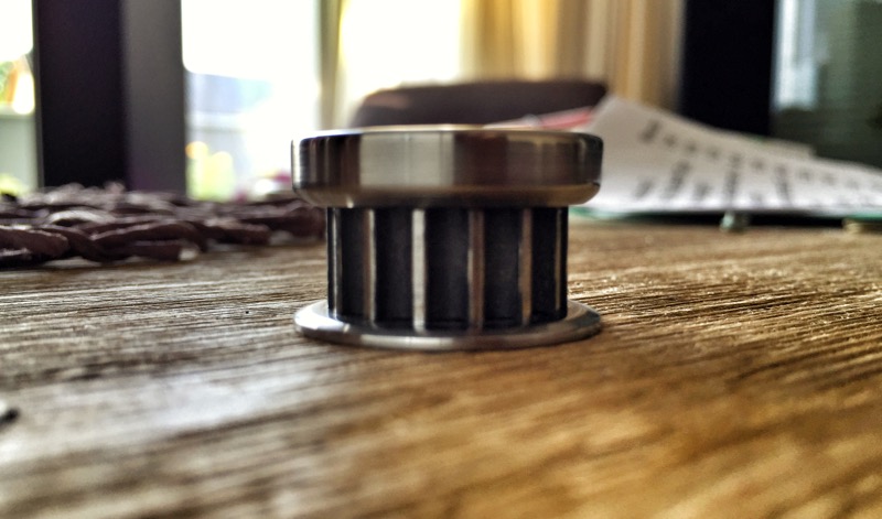
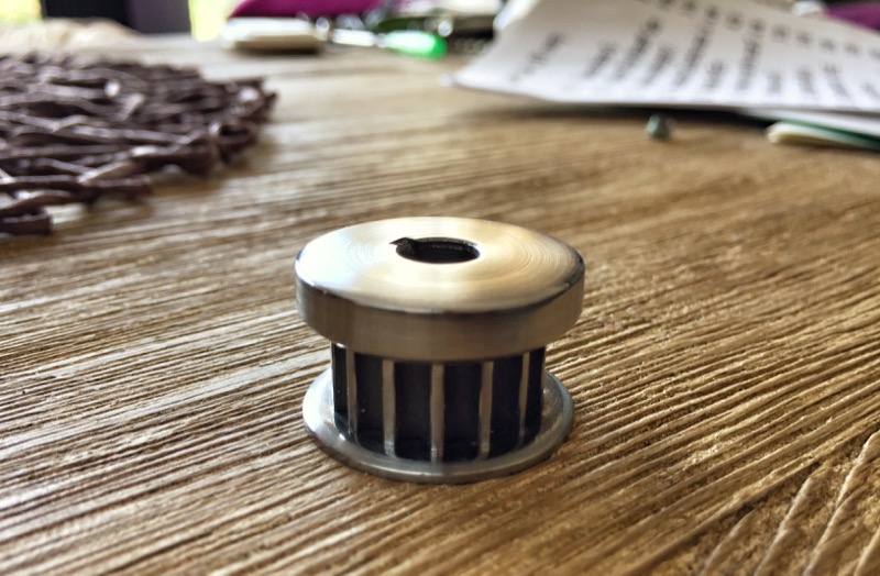
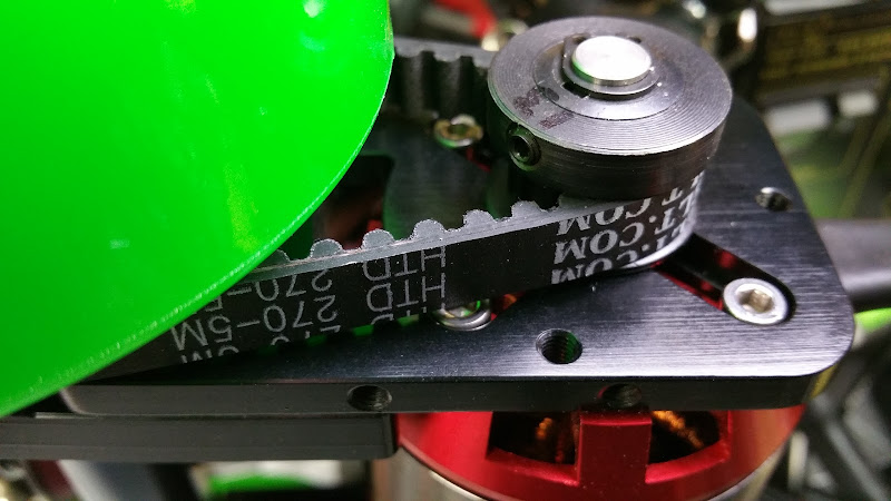
waiting for parts is lame :p wanted to fiddle anyway, so I decided to use my grandpa's self-made lathe to upgrade the pulleys to "precision" pulleys with a really beautiful brushed surface. also smoothed out all areas where the belt will touch! :)

Pulley1.jpg


Pulley2.jpg
 
i just wondered what kinda work there is for people who do physics anymore. i do hate writing code and could never do theoretical stuff myself because i don't have the skills. had to write some simple code when i ended up as end of line process engineer to find how to analyze process yield problems. the height of my math skills was learning to integrate around a singularity. and never had cause to use it beyond homework. or solving the scattering matrix that rutherford could do 100 years ago when i took QM. i did like materials so i got to do solid state and nuclear but the nuclear industry was eliminated in the public hysteria following the accident at 3 mile island. i had studied bacterial genetics for awhile and got back into physics by accident while taking a biophysics course so ended up in thermo and statistical mechanics. this was about the time that integrated circuits were moving from large scale to VLSI and i lucked out because i ended up in the same location at CSU (fort collins, colorado) where H-P had a development group to build VLSI parts so they could get into the lead on the computer business. they took me on when they were desperate for bodies to bring the process up from development to manufacturing the first really good VLSI parts in 1981. so that was where i made my mark. invented the planarization process step for the level 1 oxide back in 1983. so i am glad to see you get to do neat stuff. so many people i knew in physics never got to do the stuff they were trained for. but i think the training is what creates that extra level of insight that does not come from studying just math or game theory. i really liked materials and solid state and was really lucky to have some great professors. people who really did change the world.

i did not post that up to diss you but again i am trying to get people to think different about putting a pack together from the common way it is done. i have posted on almost all of these NCA can threads. the soldering heat is especially bad on the negative electrode. that is where the carbon is located, on the copper surface and so the heat there increases the parasitic reactions that grow the SEI crud to obstructive levels and can reduce capacity. so i try to get people to solder to the edge so there is more mass to carry the heat away along the side of the can. but spot welding is the preferred technique i know. but i look at the contact area of the spot welds and it is actually small compared to the contact area of a small solder spot of just 2mm diameter. so that is where i wish people would work. i still think the localized heating from spot welding is underestimated also but it is fast and is the industrial process. with nickel instead of copper you give up conductivity but the nickel straps are hugely wide so it is not too much of an issue. the contact area inside the spot weld is the limiting function. all jmho.
 
okp made me wanna try laminating, so I did. screwed up the corners, so Ill most likely do it again very soon ... but Ill let it dry for now and see what I can do with some sanding. :)

any tips on corners? I used scissors and made a cut, but the sheets were losing fibers then and it all went to hell. maybe i should try next time without any cuts? or I need to be a lot more careful! OR I shouldnt just try a simple box, but something rounded instead ... :wink:

made some box-mold from cheap hard foam - didnt want anything fance, just a flat box:
laminate_model.jpg


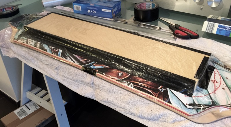
fixated it on the board, decided against the foil and taped everything instead:
laminate_tape.jpg


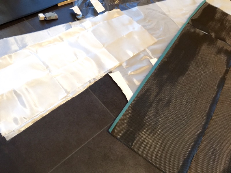
precut glas and carbon sheets:
laminate_glasscarbonsheets.jpg


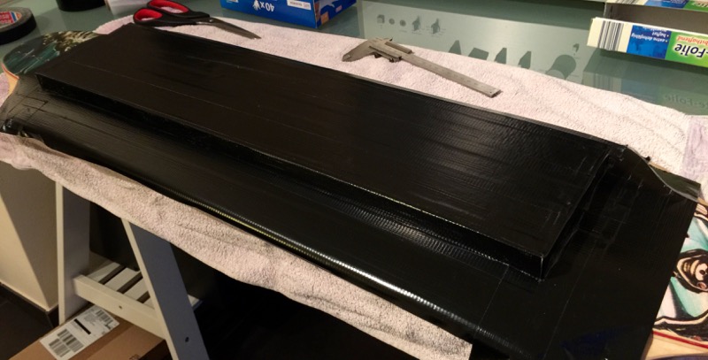
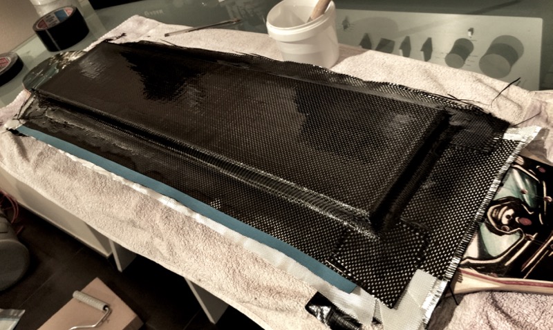
and laminated slowly - 2 layers of glas fibers, 1 layer of carbon for finish:
laminate.jpg
 
otherwise basically all parts are there :)

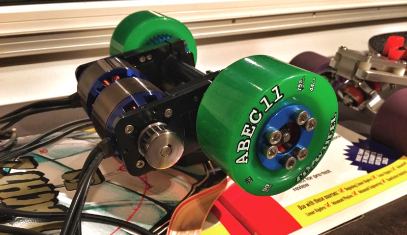
torqueboard motormount, enertion motor, 265mm belts were too short like okp already noticed - waiting for 280mm replacements now:
motor_motormount.jpg


the electronic setup: wiiceiver with nyko kama nunchuck, 2x torqueboard opto esc with 12S ubec, my diy battery and a switch:
electronics


must say all parts have a very thorough and solid touch. torqueboard motor mounts are just beautiful, the whole electronic package is set up with all the cables you need, everything is connected with large 5.5mm bullet connectors, the anti spark switch is really really heavy and well made (looks a million times better than my evolve stock stuff), wiiceiver connected with my nunchuck right away, enertion motors look really solid and sport nice silicon wires with bullet connectors too. really everything is giving the impression of a lot of effort and zero compromise, love it!
 
really clean ! congrats :D

I would have gone also rounded corners to make things smooth; just sand the corners on the foam mold. You can use only clingfilm on the deck and mold to protect it but this one is also a good idea. You work area is really neat!
 
whitepony said:
otherwise basically all parts are there :)

torqueboard motormount, enertion motor, 265mm belts were too short like okp already noticed - waiting for 280mm replacements now:
motor_motormount.jpg


the electronic setup: wiiceiver with nyko kama nunchuck, 2x torqueboard opto esc with 12S ubec, my diy battery and a switch:
electronics


must say all parts have a very thorough and solid touch. torqueboard motor mounts are just beautiful, the whole electronic package is set up with all the cables you need, everything is connected with large 5.5mm bullet connectors, the anti spark switch is really really heavy and well made (looks a million times better than my evolve stock stuff), wiiceiver connected with my nunchuck right away, enertion motors look really solid and sport nice silicon wires with bullet connectors too. really everything is giving the impression of a lot of effort and zero compromise, love it!

If you can find 270 or 275 belts they will fit better and keep your motors closer to the truck (more adjustability outward as belt wears too). I have an almost identical setup (same motors, mounts.) not sure which gear (# teeth) you are using on the front/motor.

Nice build! Love the pics and polish on that front motor gear!
 
whitepony said:
which teeth are you using? I got 15/36T right now

I'm geared down for 12s, so front motor pulley is 13t. Torque's wheel gear is 32 or 36t - i have the same. I can *almost* fit a 265, but the 270 fits perfect.

My speed calculator shows:
97mm flywheel
12s
13t motor pulley
32t wheel pulley
_______________
34mph (last time i checked on other board it was *really* close to accurate)

Or with 36t wheel pulley: 30mph

I'll likely test with 8s which tops at 20mph on 36t, 23mph w/ 32t. Plenty fast for me... I might configure a max RPM in VESC for 12s.
 
im confused now, are you using 13/32 or 13/36? was thinking about changing my order at first, but if you say 270 fits 13/32 perfect then ill just stick to 280 fpr my 15/36. if you mean 13/36 fits perfect with 270, I would consider switching to 275 for 15/36!

my setup should end up at 48kph/30mph with 190KV enertion, 10S battery, 15/36T gearing and 90mm abecs!
 
whitepony said:
im confused now, are you using 13/32 or 13/36? was thinking about changing my order at first, but if you say 270 fits 13/32 perfect then ill just stick to 280 fpr my 15/36. if you mean 13/36 fits perfect with 270, I would consider switching to 275 for 15/36!

my setup should end up at 48kph/30mph with 190KV enertion, 10S battery, 15/36T gearing and 90mm abecs!

Sorry i wasn't sure if Torque's wheel gear was 32 or 36t. So when i saw the picture of it i counted and it is 36. So my setup is 13/36:
20150904_180228_001.jpg

20150904_180359.jpg
 
This board will fly ;).

Amazing job, and the battery pack you made... Damn i want it.

Can't wait to see some photo of the entire setup when you finish it (in the garden like the first post is a nice spot)
 
first startup:
[youtube]vmLroDEOCSM[/youtube]

works flawless, LOVE the wiiceiver nunchuck combo.

* normal throttle fades in acceleration quite elegantly, but breaking isnt filtered and the raw throttle input is used right away
* press C and its on autocruise, no need to hold throttle anymore, it will just keep the current rpm.
* press throttle up/down while C is pressed: increase/decrease rpm in small steps.
* press Z and throttle: raw out, no filtering, basically full throttle for experts. breaking always goes through as raw.

really really sweet - most often I just carve hard at one speed, so this C button is a revelation for me! great package torqueboards :)
 
Wow the autocruise is really nice, didn't know that it is possible.
 
There's a few issues with the Wiiceiver. Connection can drop due to interference and/or Nyko Kama Receiver and Transmitter issues.

Also the chuck needs movement every 5 seconds, you can't hold it completely still or it will think it dropped connection.

Keep Wiiceiver away from motor wires and other wires within the enclosure. More city areas seem to have much more issues.

With Ben's and Jacob's new PCB and changing it to 2.4ghz should be real nice.. Although, I think it's only working for VESC at the moment.

As for brakes, keep brakes fairly low so you can go 20-25mph and just pump the brakes and it shaves on speed.
 
ah well, if I find life threatening signal drops Ill jump on the GT2B->BadWolf train! compared to the other components, sender/receiver is comparably cheap 8)

been spending my time with sanding the laminated case and DOH, I managed to screw it up TWICE now!!! think I need to work more with my hands than with a sanding machine. Basically I ended up with sanding "holes" into the case ... the layers are pretty thin after all. main issue while laminating are the sharp edges of the most simple cuboid form. I really dont want to make the case larger than necessary, but for laminating, I probably really have to go for something more rounded and smooth.

or maybe Ill just build my own vaccum ABS table afterall OR I order one of those vaccum bags to force the carbon & glas layers to follow the mold better. but since Ill have to wait for the larger belts anyway, I got all the time in the world to figure something out and keep working on that case.

also, I cant programm the ESCs yet for some reason. the programming card has one empty pin slot that you can usually use to connect a power source (the other 3-pin input is needed for the ESC which does not carry any power due to opto-type). tried to power it up via USB on my laptop, but when I do it like that it wont connect with the ESC. :?
 
sl33py, you were definitely right about the belts ... I ordered a pair of 280mm from a german seller and they are really generous - if I want to optimise room under the board (which I kind of have to with the large dual ESC and 10S4P battery), I will swap them for 275mm belts. returning the 280mm tomorrow and ordering 275mm for the 15/36T layout.
 
whitepony said:
sl33py, you were definitely right about the belts ... I ordered a pair of 280mm from a german seller and they are really generous - if I want to optimise room under the board (which I kind of have to with the large dual ESC and 10S4P battery), I will swap them for 275mm belts. returning the 280mm tomorrow and ordering 275mm for the 15/36T layout.

Bummer! Sorry to hear that. I wonder if Torque has any table of gear to belt size? The constant being his motor mount and 36t wheel?

so my 13/36t setup uses a 270
Your 15/36t uses 275
I'm guessing 16+t/36 would be 280?

If someone is able to find a 12t motor gear, perhaps 265 belt?

If we can build a simple matrix like this it should help the next guy so he gets the right belt the first time!

Can you show us more on the enclosure you've made from GF/CF? How stiff is it at 3 layers? Your layup is 0*, 45*, 90*? I'm looking to do this as well for another board and curious on strength and # layers used.

GL!
 
its complicated with the case - I dont want to make it larger than it needs to be and anything rounded I put in will increase the space ill need. since I kept screwing up my case with sanding I want to remake it by now ... but for the next shot I either want a vaccum bag so that the GFK/CFK layers will be properly connected and without air bubbles even at the edges and corners OR ill just build a cuboid case from GFK plates and aluminum tubes with a cut in thread. decided to go for the latter first now, GFK plates and aluminum pipes are really super cheap and this way of constructing has one advantage: I dont need a silly edge around the case to fix the case on the board with screws & co, so optically it appears to be smaller.

probably work on it on the weekend :)
 
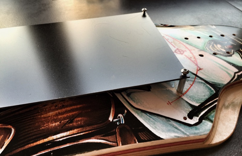
for now this is probably going to become my case - think Ill even start completely open at the sides since I havent been caught by rain yet on my evolve, nor do I ever intend to drive during wet roads or rain.

just a cheap GFK plate, 2mm thick, cut 4x 6mm aluminum cylinders with 4mm inner diameter from a 1eur aluminum pipes (will add 2 more in the middle, so 6 in total). using M4 screws that go GFK -> aluminum pipes -> threaded inserts that I sank into the boards first 4 wood layers.

the battery is trapped by slight pressure of the GFK plate and the 4 aluminum cylinders, the ESCs will be attached to the GFK plate with screws.

gfkcase2.jpg


gfkcase1.jpg


this "case" would NEVER work for a flexy board obviously, but with the top speed Ill probably get away with it! think this is the slimmest possible case for now - and most likely also the cheapest! for the future Ill either get a vaccum bag or an ABS vaccum former. wouldve tried that one, but my kitchen oven isnt large enough for 60cm. :|
 
Back
Top