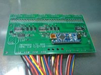
Linear Tech 12-cell battery monitor/BMS

TI has a similar part that I've demod that I like alot as well its the BQ78PL112 and BQ78pl114. I'm happy to see some more sophisticated BMS being utilized. TI has pretty much an identical chip too but I haven't designed with that one at all. The charge pumps on these for cells balancing is done really well. On top of that the these chips have impedance trac technology which all for fuel gauging without dumb coulomb counting and full cycling. They're like 10x more complicated though.

It sounds like other people have been working on some boards but I am willing to do some layout to help the effort if thats any use to anyone. I would love to see a standard come out (like an SMBus standard) which could allow any cycle analyst type device to read the SMBus type data (even if its not technically an SMBus implementation). This is juicy.
 
grindz145 said:
I would love to see a standard come out (like an SMBus standard) which could allow any cycle analyst type device to read the SMBus type data (even if its not technically an SMBus implementation). This is juicy.

I think that is up to us.
We have to set the standard so that the smart guys can come along, leverage our ideas, and make lots of money :)

-methods
 
grindz145 said:
TI has a similar part that I've demod that I like alot as well its the BQ78PL112 and BQ78pl114. I'm happy to see some more sophisticated BMS being utilized. TI has pretty much an identical chip too but I haven't designed with that one at all. The charge pumps on these for cells balancing is done really well. On top of that the these chips have impedance trac technology which all for fuel gauging without dumb coulomb counting and full cycling. They're like 10x more complicated though.

It sounds like other people have been working on some boards but I am willing to do some layout to help the effort if thats any use to anyone. I would love to see a standard come out (like an SMBus standard) which could allow any cycle analyst type device to read the SMBus type data (even if its not technically an SMBus implementation). This is juicy.
For the past few months, I've been working with the bq78PL114/bq76PL102 combo on my own board (after playing a lot with the eval board) and I can say it's an incredible chip. But, you're right, it is 10x more complicated than the LTC6802. Not only in the board design and layout but in the firmware settings (over 200) and multiple configuration files needed to set up the chip. One wonderful advantage of the TI chipset is that the charge-transfer balancing can take place at any time; during charge, at rest, during discharge. And the balancing can be done not to the open-circuit voltage but to the individual capacity of each cell, even as the cell ages and the internal resistance changes.

But, it's a real bear working with this chip. And, the cost for the boards and the setup and testing needed to match it to the cells being used make the LTC6802 a much better choice for the vast majority of applications. I'm working on a very specific app for a client that makes the TI chip set the better solution but I'm really looking forward to seeing method's design come to light!
 
Due to cost constraints I think I am going to have to eliminate the RC circuit on the front end... it is just too many parts - it nearly doubles my part count for automated assembly - which basically doubles cost. I am really apprehensive about how this will shake out - the accuracy is amazing sitting here on the bench but I am wondering how accurate it will be with a controller pumping mega-noise through the cells and no RC on the front end.

I guess the only time that we really *need* accuracy - while the controller is running - is when we need to detect cell level LVC.

-methods
 
CamLight said:
grindz145 said:
TI has a similar part that I've demod that I like alot as well its the BQ78PL112 and BQ78pl114. I'm happy to see some more sophisticated BMS being utilized. TI has pretty much an identical chip too but I haven't designed with that one at all. The charge pumps on these for cells balancing is done really well. On top of that the these chips have impedance trac technology which all for fuel gauging without dumb coulomb counting and full cycling. They're like 10x more complicated though.

It sounds like other people have been working on some boards but I am willing to do some layout to help the effort if thats any use to anyone. I would love to see a standard come out (like an SMBus standard) which could allow any cycle analyst type device to read the SMBus type data (even if its not technically an SMBus implementation). This is juicy.
For the past few months, I've been working with the bq78PL114/bq76PL102 combo on my own board (after playing a lot with the eval board) and I can say it's an incredible chip. But, you're right, it is 10x more complicated than the LTC6802. Not only in the board design and layout but in the firmware settings (over 200) and multiple configuration files needed to set up the chip. One wonderful advantage of the TI chipset is that the charge-transfer balancing can take place at any time; during charge, at rest, during discharge. And the balancing can be done not to the open-circuit voltage but to the individual capacity of each cell, even as the cell ages and the internal resistance changes.

But, it's a real bear working with this chip. And, the cost for the boards and the setup and testing needed to match it to the cells being used make the LTC6802 a much better choice for the vast majority of applications. I'm working on a very specific app for a client that makes the TI chip set the better solution but I'm really looking forward to seeing method's design come to light!

Impedance trac is incredible, but I agree with you for the investment as it applies to electric bikes specifically, it's probably not worth it. A simple Cycle Analyst type device is more than enough in most cases as far as fuel gauging goes.
 
Unfortunately for the time being I can no longer work open source. Not my choice (and in my opinion not a good choice) but it is what it is.

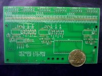
To give a sense of scale - the pitch on U1, U2, & U3 is 0.5mm
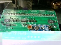
Should be populated by Sunday - though this design (obviously) was set up for automated assembly.

Please don't ask for any details (for the time being).

004_Methods_LTC_BMS_V1.0.jpg

-methods
 
Oh no, the evil forces of secrecy and proprietaryness have descended. Sorry to hear that methods - hope you are let out again sometime soonish.
 
Methods, good luck in the testing of V1.0!
I understand the position you're in and that you can't release any more info.

Posting that PCB photo was just cruel though. :mrgreen: :mrgreen:
 
I will have fully populated pics tomorrow :p

-methods
 
Theres no shame in not open sourcing everything. Where did you get your boards made? Do you have a plan on who you might use to populate the boards for you?

-Troy
 
methods,
I noticed you have no fiducials on the board? (The little circle marks for machine vision in Pick and Place/Stencil printer)
To build this board with a machine you'll either need them on the board itself or on panel rails, if you end up panelizing them.
 
:mrgreen:
My wife loves your work. She asks about you from time to time :oops:

-methods
 
Ok - F I N A L L Y got the comms working on the new board. I very nOoBishly forgot to account for the inversion made by my 1Mbps optocoupler. Correcting CS and CLK was easy enough (in the SPI settings) but I was left with inverting all the commands and responses in firmware. Obnoxious - but trivial in the long run.

I have connected an 12S simulator and I was able to successfully read back all 12 voltages.
Next is to test up to 36S (current comms), test the shunt mirror, test the temperature probes/conditioning, etc.
The hard part is behind us now. :?

One thing to watch out for if you are in TV land is the setting time on the A/D :idea: :wink:
If you are getting fubar data - think back to this post.

Man - I have got to say that this is not for noobs :) I have programmed many a microcontroller in my day and this setup has exercised just about every little "oh yea...." in my book :roll:

-methods
 
I too approve of the testing setup! 8)

Arduinos are loads of fun. I have several of them around for various projects. I built a follow-the-sun solar panel tilt controller for a friend of mine based on an one.

I love following this project. Those LT chips look awesome for monitoring 12s strings, I might have to look into implementing those myself. Currently I've got a setup where I can monitor 4s strings using an arduino and some voltage divider electronics. Maybe I should look at using the LTC chips; at this point I think the component count is high doing it the straight ADC way. But then again it looks like you have a pretty high component count too.

Cheers,
--Adam
 
ahambone, if you're looking for accuracy, go the LTC way. :)
You're not going to beat it IMHO with discrete electronics. Especially for any setups with more than 12 cells in series. If you only want to monitor cells, Linear has the LTC6801 chip too. I'm not sure if it's in full production yet but it would be simpler to use than the LTC6802...a bit. :)

methods, congrats on the continuing progress you're making! :mrgreen:
 
If you need some help testing-assembling-whatever I would really like to use this for an a LiMn2O4 pack I'm building. I'm trying to find a good simple/affordable 'dumb' preferably hardware programmable solution and I'm leaning toward TI...
 
The LTC chips do look sexy. I'm not sure I'm ready to make the leap to surface mount yet. My hands just aren't quite that steady. :roll:

I just ordered my first custom PCBs for battery monitoring stuff a couple of days ago (G/F BMS boards don't count). I'll see how that project works out. If I can get it working then my confidence will be high enough to maybe try the LTC chip. I'd have to make an Eagle part for it and then lay it out on a PCB. Could be really interesting for Li* cells. What I'm working on right now will monitor PbA and Li* from the same PCB with just a couple of component changes. I really like that property of the PCB + micro + passive components way.

There is one question I have - I just picked up an CA-HC rated for 200 volts. What does eBikes change to go from a 100V rating to a 200V rating? I've designed simple switching regulators that can pull 3.3/5.0/9.0 volts from up to ~50v. I don't understand what gets thrown into the mix to make those circuits safe to hook up to a ~200V input. Is it as simple as adding a big resistor? On the voltage sensing side it makes sense but on the power side it seems inefficient.

Maybe I'll pop open the CA and take a look.

Cheers,
--Adam
 
Oh.... hell yea -> Got communication running up and down the stack. :p :p :p

I have been shuffling my feet for almost 24 hours avoiding the test because I was worried that I flubbed something.
NOPE :wink:

All 36 channels are working like a champ!

SHWEEEEET!

Here she is all wired up with a 36 cell simulator.

010_Methods_LTC_BMS_V1.0.jpg

One might ask "Why do you use a simulator instead of just hooking up 36 cells???"
To that I would answer pictorially -
Here is what happens when you pull 450A from an 18S 6P pack - more specifically - with the main lines dissconnected on one pack.

002_Methods_LTC_BMS_V1.0.jpg

That is what I *dont* want to happen while testing :roll:

I say we celebrate with 3 ketchup tacos - methods spec!


Ketchup
View attachment 010_Methods_LTC_BMS_V1.0.jpg

Meat
View attachment 011_Methods_LTC_BMS_V1.0.jpg

Ketchup
View attachment 2

Cheese
View attachment 013_Methods_LTC_BMS_V1.0.jpg

Popeye


:mrgreen:

-methods
 
Congrats! 36s bms on one board is a beautiful thing. And teh comms!

What are the discharge fets going to be rated at?
 
methods said:
Oh.... hell yea -> Got communication running up and down the stack. :p :p :p


Ketchup
View attachment 2


-methods

I highly recommend PBJDillas, quesadilla maker, crunchy PB, Jelly, serve warm and gooey 8)
 
grindz145 said:
Congrats! 36s bms on one board is a beautiful thing. And teh comms!

What are the discharge fets going to be rated at?

There will be shunt pads for up to 2A balance current through four 500mOhm 2W shunts in series (only $0.08 each!). Unfortunately this burns off about 300W worst case so we will be starting with 1A balance currents and active cooling to reduce heat issues. We are working on an inductive current shuttle but that is just pipe-dreams at the moment. We have a 2A low cost inductor picked out. The basic idea is that the LTC6805 enables a surface mount 555 timer (on each channel) which drives the inductor bypass at a couple MHZ with a pair of surface mount fets. Parts count and price is comparable but the tuning will take a lot more time. All the isolation issues are handled by the LTC and each 555 draws its power (when enabled) directly from its cell. It only needs to work above 3.5V...

The fets will be 20V 4A continuous surface mount with OV diodes for protection (just like the DC11331).

I am thinking about adding one more LTC to cover the majority of EV's up to 144V LiFe. Wont really cost anymore if the pads are not populated.

-methods
 
So there are no output isolation FETs then? I am used to having a Fet on the stack for the total output of the pack for protection. Safety is the main concern when I'm thinking about BMS design, but this seems to be intended for cell health (balance) and monitoring primarily. The basic cutoff function really needs to be handled in by the controller and other fuses when the pack is this size though I suppose. I'm also not used to working with cells that aren't prone to thermal runaway :lol:
 
Back
Top