Linear Tech 12-cell battery monitor/BMS

Good find on the ebay thread!

Wow - I read the fine print: $58 for air shipping if you want them ASAP.

20 chips * $26.80 = $536
+$58 = $594 ouch!
That man is making some serious scratch.

My source for 10 turned out to be 3 - but at least they will be here tomorrow!
The first 3 are the real killer... That is all I need to populate 1 more board.
Absolute worst case I always must have 1 board on hand and 1 board back up in case I blow smoke in the middle of the night.

-methods
 
I think i have 4-5 LTC-6802-1 in a tube. serveral more on boards. Also, have one demo board from LTC. I've not been successful removing chips from boards.

Suggestions for improvements to your ckt (from experience):

Use both protection zeners that are used on the LTC-6802-1 Demo Board ckt from LTC.

For a balancing PFET, use FDN304PZ. Smaller package, will handle up to 2 amps,
Instead of the smaller SM chip load resistors, use mouser pn 66-W224R70JRLF 4.7 ohm. Just right for any size battery. Put a standoff and get some air flow under.
This is a wirewound resistor, so use a shunt diode, such as a 1N4935-E3/54 to catch the reverse spike when your fet opens, or you will fry some LTC chips.... promise.

Mark.
San Diego, CA.
 
hardym said:
I think i have 4-5 LTC-6802-1 in a tube. serveral more on boards. Also, have one demo board from LTC. I've not been successful removing chips from boards.

sweet.

hardym said:
Suggestions for improvements to your ckt (from experience):

Ok - go.

hardym said:
Use both protection zeners that are used on the LTC-6802-1 Demo Board ckt from LTC.

I am. I use all of the "extra stuff" that was used on the demo board. The 6.1V zeners, the 12V zeners, the current limiting resistors, the ESD protection, - all of it.

hardym said:
For a balancing PFET, use FDN304PZ. Smaller package, will handle up to 2 amps,

I use a surface mount 2A pfet from IR that is under $1. I would be willing to compare specs - I suspect mine might be better but I have not looked closely.

hardym said:
Instead of the smaller SM chip load resistors, use mouser pn 66-W224R70JRLF 4.7 ohm. Just right for any size battery. Put a standoff and get some air flow under.
This is a wirewound resistor, so use a shunt diode, such as a 1N4935-E3/54 to catch the reverse spike when your fet opens, or you will fry some LTC chips.... promise.

Just right? Assuming you want under 1A shunt current and you have a zero vibration environment. I have 1.2A shunt current and a very high vibration environment.

I dont quite understand this piece of advice... my smaller chips cost pennies while your large wire wound costs dollars. The surface mount take up less space - both in footprint and vertically. The wire wounds are big masses prone to vibrate loose. Since they are singular you cant adjust the current at loading time. Since they are wire wound now you have to run 36 more shunting diodes..... so -> costs more, takes more space, less reliable in vibration, fewer options, much less shunting current - I dont get why I would want to do that. :?

Currently I can keep the surface of my surface mount chips at around 70C - they are rated for 155C. I can adjust my current from 200mA, 400, 600, 800, 1000, 1.2A. I can mount the fans right on top of them, they wont rattle loose, they cost pennies on the dollar, they dont have inductive qualities so I dont need the diodes.

I think you should switch to my shunt resistors ;) They only cost $0.40 per channel. Sounds like a slam dunk to me.

hardym said:
Mark.
San Diego, CA.

Anyhow - welcome Mark!

-methods
 
Hey everyone,
I'm a member of the UC Berkeley solar car team. We are trying to use the LTC6802-1's for our battery protection system. So, a few of us each got a chip and tried to just get that one chip working before we tried to daisy chain them. But, we can't get SPI to work properly. I think our code is correct, since we checked it against some of the code a few pages back that seemed to work for methods. This suggests a hardware problem. Basically when we try to read any registers over SPI, every bit shows up as a 1. Since I'm pretty stumped, I was hoping someone here might have a suggestion. The following pic is a schematic of the setup that we did based on the datasheet specs. Although, where it says 5v on the micro-controller it should say ground. Also, we have 4 cells hooked up, not just 2 so that we can get over the 10V min.

27234_431554365128_689080128_5728643_7999792_s.jpg


Any ideas?
 
Thanks guys - not sure why I am not getting my email notifications again :?

I have about 1,000 pictures and a bunch of movies but no time to post.
Here are the highlights:

* System is working well.

* Batteries are now Schottky isolated - this allows me to leave the fans and charge control circutry connected. I used a 250V 45A Schottky. It stays cool under the fans.

* Charging has been tested up to 3C on 24S. Charging 5Ah packs at 15A makes the system way under-damped but it works. The system works much better charging 24S 15Ah at 15A 1C.

* System detects when all cells are within 0.005V and turns off the shunts and charger

* Charge throttling is working but at a very slow PWM. Faster PWM's cause noise on my comm lines that I dont have time to troubleshoot but the "area under the curve" is the same so the charge process is just as fast.

* All the safety detection systems work great - nothing (so far) can trick it into shunting when it is not supposed to or driving current when it is not supposed to. The uController is electrically isolated from everything so it is fairly immune to anything going on in the circuit. The charge throttling is also electrically isolated from the balance section so the only time it interacts is when it actually starts to operate.

* Shunts are doing well over 1A and surface temps are staying under 70C

* 4115's are cool as ice and the LTC board never gets over 50C (good up to 85C)

* Housing stays cool to the touch and is electrically isolated.

* Boards mate together and fit in the housing with minimal BS. Housings are machined to fitted with 2 x brushless fans. Fans mount with nice rubber plugs similar to what is used on a PC.

* Bottom of housing slides off to allow access to connectors

* I have 1 unit built up and enough populated boards to build 3 more.

* Pics and vids soon

-methods
 
OK - I will share some of what I have learned with my fellow LTC geeks.

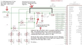
I have not posted much about it here but it turns out that high frequency PWM is causing excess current to flow on the comm lines between my LTC chips. Running only 12S I have no problems at all - but as soon as I step it up to any voltage that involves two chips trouble starts:

* communication becomes unreliable
* High current flows on the comm lines (which are already "current controlled" for isolation)
* Resistors get hot and smoke off between chips
* Chips get hot and (possibly) damaged

The work-around was to lower my PWM frequency (this is the charge throttle PWM btw) to around the HZ range. This kind of slow switching eliminates the problem and my system works perfectly. But... I still want to do smooth PWM so ...

I got to thinking and did some reading... Up till now I have followed the demo boards fairly closely - but in this case I think we need to do a little something different. The Demo board links one LTC to the next via an RC filter resulting in 20 ohms between the two chips. I think this is causing the issue - so I am going to add a hard redundant current path between the V+ of each chip and the ground of the chip above it.

I suppose you might ask why I am talking and not doing... I am stuck at work :(
They can make me stay here but they cant stop the electric revolution from going in my head :D

PWM_FIX.JPG

-methods
 
methods said:
Thanks guys - not sure why I am not getting my email notifications again :?

I don't get all of mine, either, so I started just using these two links to check every day instead:
http://www.endless-sphere.com/forums/ucp.php?i=main&mode=subscribed
http://www.endless-sphere.com/forums/ucp.php?i=pm&folder=inbox
That way I can see what's new in my threads and PMs and go straight to them. If I have time I can also go here:
http://www.endless-sphere.com/forums/search.php?search_id=newposts
to see what's new outside of those.


I wish I had help for the other problems, too, but they're beyond my 21-year-old electronics design skills. :(
 
View attachment 001_methods_LTC_BMS_V2.0.jpg
002_methods_LTC_BMS_V2.0.jpg

The back cover slides off real sexy like. . . Later there will be a lot more cabling - there are still 8 temperature sensors and a current sensor to hook up.

View attachment 5

Here is where I kluged in the 250V 45A Schottky diode on the charge line. This stops the battery from being discharged by the fan, 12V regulator, 5V regulator, opto-coupler, mosfet driver, or any load that a charger in the off state could apply.

View attachment 4
View attachment 009_methods_LTC_BMS_V2.0.jpg

The fans attach with some nice rubber peckers and the shroud is a 3-piece setup. You solidly attach the part shown below and then you have the option of running the additional filters. Could be nice if you have to charge the pack in a hostile environment.

View attachment 011_methods_LTC_BMS_V2.0.jpg

These prototypes are a little off - but a 2" 3/8" hole saw is perfect for these fans. Shown are 2" - those have a nasty lip that restricts the flow.

View attachment 012_methods_LTC_BMS_V2.0.jpg


-methods
 
Pshh... it's all just photochop. No video means it doesn't exist. ;) ;)

Just teasin! It looks great Methman, it looks like the next board revision will tidy things up on the board quite a lot. :)

-Luke
 
Very nice. I love these Hammond boxes. Which size is this one?

Yipes, those fans are huge! :shock: Are you planning to have it levitate? :mrgreen: They will definitely keep things nice and cool, though.

Very nice work. :)

-- Gary
 
That is the 6.30 in. L x 3.07 in. W x 1.69 in. H

I am balancing 36 cells in there..... 4.2V * 1.2A * 36 = 181W
My resistors are rated to 155C so I spec'ed the fans to keep the resistor surface temps at 70C (in 20C ambient air)
This leaves tons of margin for being mounted in the semi-enclosed environment.

What do the surface temps of your cells get up to at ambient and what are they rated to?
Are they still within specification if you enclose them in a large container with other heat creating devices? :)

My worry is having the solder melt :shock:
155C is already 311F.... that is close enough to melting!

Another aspect are the temperature ratings of the chips.
The LTC chip for instance is rated to 85C (though it will work up to 105C no problem).
If I let the shuts get all hot and bothered it will start to affect the other parts of the circuit.

Go check the DIY-BMS thread on DIYEV. Read that white paper (just posted as a rebuttal to my high balance currents) where the guy is arguing that a 10KW pack only needs 100mA balance current.

His argument is compelling - though I am sure he must be from a different planet.
At first I thought he was arguing for high balance current... then I read it again.

I suppose if you are always balancing then a couple hundred ma is acceptable (for normal folk).
I am Gangster though - gotta have 10A balance current else Luke and that guy from the kangaroo island may think I am a ninny.

-methods
 
Yes, this ought to be "gangsta" enough even for Luke to pee a little. :roll: :lol: He'd probably want to mount this on its side, with the fans facing backwards, so he can get the extra thrust. :mrgreen:

Surface mount definitely makes things smaller, that's for sure. In that same box I can only fit 12-channels of the analog through-hole BMS.

I'll go check out the DIY thread over there later, when I have time. Generally, I find that what these guys are doing is not too relevant to my own setups. I'm all about LiPos, like you, and it seems most of their setups use the large format TS and Sky Energy LiFePO4 cells, which seem to have significant capacity and/or IR differences, so balancing is required a lot more often. My 18s2p and 24s3p Turnigy/Zippy-based packs almost never need balancing, unless I run the packs all the way down to where the individual cell LVC circuits start tripping. This is why I only put LVC/HVC boards inside my packs. These work perfect with the small standalone charge controller, which simply has an adjustable current limiter and using the HVC opto signal, individual cell CV modes. For balancing, all I'm using now is a single hybrid Battery Medic, with a simple analog shunt booster. This combo allows me to also have about 1.2A of balance current (200mA in the BM itself, and 1A+ in the booster...) while eliminating all the analog oscillation and voltage drop issues. The "digital" BM does all the voltage sensing/measuring, all the booster does is turn on a shunt (and an LED...) when the BM turns on its shunt. This works extremely well, but using through-hole parts make the booster bigger than it would if your SM approach was used. :)

-- Gary
 
Oddly enough - I have two guys criticizing my design for having too high of balance currents :| (that is the last thing I expected to hear)
They are both arguing that lower balance currents and a passive analog design is the way to go.

Maybe you can sell them some V2.1 BMS's :p

Of course... both of the guys sell their own BMS's so....... :roll:
Everybody understandably likes their own design.

Another aspect is that they are targeting "normal people" with "OEM" type stuff while I am targeting people like Luke who just found 75KWH of lipo that rolled off the back of a truck and want to charge the cells to 4.5V.

-methods
 
The BMS arguments go on quite a lot, especially at places like DIYEC. :)

Based on past things I have read, I think part of the reason lower balance currents are used there is to *enable* the use of cheap, simple, small, cooler-running analog shunting, stuff that can typically be left bolted right onto the cells at the terminals, with small short connecting wires.

A centralized high-current shunt system requires larger wires running from potentially multiple sources in a typical conversion vehicle (trunk, engine compartment, under seats, etc.) to a single location, because there is often not room in any one place for all the cells they need to use. Or the weight distribution requires not having them all in one end of the car.

Of course, if you have a shunt board for each compartment of the vehcile, keeping the shunt wires shorter, and just centralizing the *control* of the boards, it simplifies some of that wiring.

So those are probably some reasons why they're thinking of lower balance currents and simple analog systems being better, when in fact it depends on the purpose for the vehicle, user preference, possibly even cell type.
 
I agree - it is all about application.

For me - I would go ape-shit if I had 200mA balancers even on my 10Ah bike pack. To think of using 200mA to balance my 140Ah pack just boggles my mind. I manually balanced that pack with 12AWG for DAYS and still never even got it close to balanced...

There may be a difference in definition of "balanced" as well... When I say balanced I mean to within 0.005V. I think many people are happy to get within 100mV. That may be OK with LiFe - but with a chemistry like Lipo where all the energy is up top the difference between 4.15V and 4.05V can be the difference between riding in style and trying to find a 1,000' extension cord to charge up with :p

I do recognize the simplicity aspect though. I really like the idea of little nodes on the large format cells. Clean and easy - no wires - no programming - no mess - no BS.

Maybe I will make one of those too :)

-methods
 
That is a *very* nice BMS, Methods - I bet those two guys just have "design envy"! :)

Anyways, after reading a little of this thread I see you guys were talking about the standby current of various BMS circuits a few pages back. Your BMS draws about 200nA standby current - While doing a few tests on some 116 based controllers (EB212), I noticed that leaving only the main battery leads connected and with no power on the logic supply, the controller leaches 4mA from the battery. That's 20 times more than your BMS, making your circuit's standby current look like nothing in comparison. It is a 10k resistor that does this (R203), most likely put there to drain the voltage off the big capacitors when the unit is unplugged.

This means that someone leaving their main power leads always attached to their battery, and only using the logic power input to turn the controller on and off would see this much current leached from their pack:
--> 100mAh/day
--> 700mAh/week
--> 2.8Ah/month!!!

This makes me wonder how many people have killed their packs from leaving their controller's main battery leads connected while in winter storage??!

Pat
 
GGoodrum said:
ZapPat said:
--> 2.8Ah/month!!!

This makes me wonder how many people have killed their packs from leaving their controller's main battery leads connected while in winter storage??!

:shock: <rushes downstairs to check pack...>
Oh... I forgot to mention that the 2.8Ah/month was for a 40V test pack, so for people running 100V packs ( :wink: ), you might well be facing a 6Ah/month drain on your battery!
 
9C started populating that main cap bleed resistor on the 6fet boards I was getting from Justin. I think they used more like a 50K on the ones I looked at. I cant speak for other importers but on all of Justins new 6fet and 12fet boards that resistor is gone.

I would just remove that resistor if I were you guys - all it does is make sparks when plugging things in :)
You can get to it by only removing the side cover on the 846 6fet boxes - not sure about the others. It is usually standing upright.

Street tested, methods approved :wink:

003_methods_LTC_BMS_V2.0_PrePro.jpg
008_methods_LTC_BMS_V2.0_PrePro.jpg

-methods
 
Hello Method,

Good work on your BMS. I like your thinking with the 20amp shunt current. I support you all the way for that idea.

I see you have 5 x 20ohms in parallel shunt resistors. at 1.25amp each resistor is only getting 250mA of current. or dissipating 1watt of power. why does it get so hot at 150degree with 2 big fans blowing on it? if they are rated at 1watt shouldn't they stay at like 70degrees?
 
ricksta said:
Hello Method,

Good work on your BMS. I like your thinking with the 20amp shunt current. I support you all the way for that idea.

I see you have 5 x 20ohms in parallel shunt resistors. at 1.25amp each resistor is only getting 250mA of current. or dissipating 1watt of power. why does it get so hot at 150degree with 2 big fans blowing on it? if they are rated at 1watt shouldn't they stay at like 70degrees?

They are 1 Watt resistors and I designed it such that they burn under 1 watt each. With the fans blowing the resistors stay under 60C (surface temp) at 25C ambient and the case never gets over 35C.

If you read the data sheet you might think that you can actually run a 1W resistor at 1W but that is not the case - nor is it the case with any part (mosfets etc). It is assumed that you have a certain amount of heat sinking through the pad contacts on the board. There is enough data in most datasheets to calculate just how much pad you need.... but I can assure you that when a component is rated they are very generous to themselves.

This power rating is also assuming you have a 25C ambient. What happens when you put 190 1W resistors in a small box and run them at 1W? Well... that 190W is going to heat the box up FAST. Now Ambient is no longer 25C, now it is 100C, then 150C, then.... You see we are adding energy to the box from the pack right? Without a VERY large heatsink - where is that energy to go?

Take for instance a 180A IRFB 4110 mosfet.
How long do you think you can run 180A through there before it overheats? (about 1 second tops)
How about even 20A?

So - the deal is that parts are very misleading in how they are rated. It is important to know what the ambient temperature is, how fast you are warming up that ambient, what the C/W is of the part, and a bunch of other stuff.

So - to answer your question - those resistors hit >150C in about 5 seconds without the fans. :shock:
Believe it or not - I can show you a video if you like.

The original design called for two much smaller fans that fit inside - but even with them blowing full blast the surface temps rose to over 120C at ambient. Now imagine how hot ambient can get if you are stuffed inside of a motorcycle gas tank running all those resistors for 5 hours.

I think that if you analyze many BMS designs you will find that they are running their axial resistors WAY hotter than they are rated for. This heat is very damaging - bot to the resistor and all the parts around it. It is very important to keep a circuit running at a cool consistent temperature if you want consistent results. For instance, the LTC is only rated to meet spec at up to 85C. If I heat-sunk those resistors down thru the board or into the case the LTC would quickly heat up to the point of providing less accurate readings. As it stands - I have a temperature probe on the LTC and it is no warmer with the shunts on that it is without. This thanks to the fans.

-methods
 
BTW: I delivered the first BMS to the customer and the initial tests were a success.

I have the charge throttling working in "limp mode" at about 25hz. The next big hurtle is to figure out why I am getting so much noise on the LTC communication lines when I run the PWM faster.

I have 4 units built up - and I have rebuilt 1 of them (mine) at least 3 times after doing amazingly stupid things (like plugging the 100V tap into the 50V slot) :roll:

-methods

EDIT: P.S. The bug is running :p Pictures later.
 
how loud are those fans? I remember the computer I had 6 years ago was super loud with it's big fans, and it got hella annoying.

can those resistor be heat sinked? i guess the heat sink will be a tricky design.

what about submerge them in oil? they are computer built with oil filled cases. supose to be pretty good at keeping it cool. Then you can up the current even more if they stay cool right?
 
Back
Top