Lishui "Open Source Firmware" project / KingMeter 5S

Is it possible that you can help me a bit with this task?
I think it would be much easier to spent some Euro for buying a cheap display, that uses the 5s protocol.
But first check, if the motor connector has only 3 pins. If it is a sensored motor (9pin motor connector) you can use the master branch with the Bafang display.
 
Ok, thanks! I happen to have some SW900 LCD on my desk, I can see that under P20 I can select beteen 2 and 5s protocol - so this is indeed the easiest way to do. The last question is how to flash sensorless FW, since it does not have this java tool?
Thanks a lot for help :)

Edit: I am following the wiki assuming that I am flashing controller using Eclipse. I installed it but it looks different than on screens. I am struggling to make it running.
 
Last edited:
Ok, I managed to install eclipse and all components described in the manual, I managed to connect to the controller - it was not loced, so I am assuming that someone already "been there".
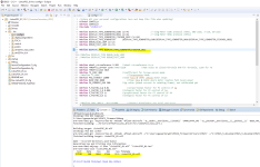
I imported Sensorless_VESC, in config.h changed display type from "DEBUG_SLOW_LOOP" to "DISPLAY_TYPE_KINGMETER_901U" but I have a bunch of errors in main.c

1738500367964.png

1738500398512.png
 
So apperantly the STM32 cannot handle 24v, somehow that was the reason the original mcu got killed, just like the new one. I just assumed it was my own doing but it's somewhere upstream.

Anyone recently bought any non-potted versions? And would like to tell where.

Or in case someone knows what the LSW part numbers indicate, I know F is a FOC variant and M is a non FOC motor, but there seems to be a specific 1F/2F/3F variant for most part numbers LWS[type]-[version]-[1/2/3F]. Anyone any idea?
 
Last edited:
but I have a bunch of errors in main.c
Hm, strange. Seems as the Kingmeter header file is not included. Did you crosscheck the include pathes in the project settings?
For me, both settings, 901U and FISCHER_1822, are compiling whithout errors.


1738513083614.png


Anyone recently bought any non-potted versions? And would like to tell where.
I don't know a source for non potted controllers, but it is no problem, to remove the potting.

regards
stancecoke
 
Last edited:
It was indeed some problem with path definition, at the end errors disappeared, but even though I could not flash the controller.
For testing purposes I downloaded master branch, and flashed controller using java tool - I tried various display protocols including KM5S, JLCDKunteng - none of them seement to work with my SW900 LCD, I selected various options under P20 setting position for protocol 2 i got error 10, for 5s I got error 30. I even tried flashing Bafang protocol with C965 display and the result was the same - error 30h. To be clear - I got only controller and display on my desk connected together
i connected Tx<>Rx. I checked Rx and Tx cable continuity with ohmmeter and these are ok.
Does it mean that Tx and or Rx are fried? Would it be possible to do something with this controller or it's trash?
 
Does it mean that Tx and or Rx are fried?
Do you have an USB UART converter? Then you can listen to the data stream (9600 BAUD for Kingmeter) from the display first, if that is OK, you can listen to the answer of the controller.
It is known, that the two transistors of the level shifter from 3.3V to 5V of the controllers Tx line are quite fragile and easily break. But they can be replaced with some SMD soldering.
See the German forum:

https://www.pedelecforum.de/forum/i...bei-fischer-ecu1401-ratlos.92859/post-1785437

regards
stancecoke
 
Last edited:
Yes, I have - I just checked it, and Tx from display is transmitting all the time, while Tx from Controller remains silent. I guess I have to remove the goo and locate faulty transistor. Thanks once more :)
 
I don't know a source for non potted controllers, but it is no problem, to remove the potting.
It's not a problem per-se but the annoying design of the tubular heatsink for the one I got was a real pita to remove. I found an older 6 fet version cheap which likely does not have potting, should be good enough for what I do with it.
 
Just wondering: Do they really use a double npn configuration and not inverted signaling in software (haven't checked the code), missed oppertunity to save some money otherwise.
 
Any system that does use the double transistor is likely using it for it's buffering properties, to slightly better isolate the MCU from external wiring faults--blow up just the one transistor or even both but not hte MCU.
 
Transistor closer to STM is shorted between base and collector, and the other transistor during measurement did not resemble a regular transistor. Both were replaced with some NPN ones. Will test it later :)
BTW. marking on old transistor was G1 - anyone knows what exact model is this?
 

G1 is a quite general marking, several manufacturers use it for NPN transistors...
 
Ok, there is some progress! Instead of 30h, bafang displayed now 06h, which looks like undervoltage or so. I used Java tool to compile and flash KM5S version, and no communication error :D. I tried to turn the lights on, there is no power comming out of buck converter, but I can see a control signal changing, which means it is talking to each other.
I have yet another problem with battery - charger. The charger was dead, one capacitor in line powering hi voltage mosfet driver was partially shortened and driver was not starting. It was fixed, but now charger is not charging once connected to the battery. LED on the charger turns red upon connection, to get back green after couple of seconds. Current is 0 all the time, transistor for charging in battery is open, the same story with output power transistor in charger. except + and -, there are 3 lines: ID, COM, NTC, these play some role in charging process, but I do not know how to start investigation :)
 
Hello, I fully charged my battery and equalized it with bench power supply and then discharged it to measure capacity - it showed 9.25Ah till BMS shut down.
Yesterday brand new charger I ordered arrived, and charging is not starting, even after I charged cells up a bit using my bench power supply - I assume that BMS is crappy and since I could not find any documentation to be able to fix it, I'll get rid of it and replace with a universal 13s one.
Today I got to collect a 5 pin KM type display and will be struggling to flash sensorless fw to the controller :)
 
Hi, @stancecoke I successfully managed to flash sensorless firmware, display does not show E30. Can you tell me what is the battery current limit in this? I could not find any related parameter in the config file, there is something that looks like phase current limiter. Also is is possible to use throttle in it?
 
Can you tell me what is the battery current limit in this?
This very old branch has no battery current limit implemented. The battery current is only calculated to show the power in the display.

Also is is possible to use throttle in it?
Yes, if the torquesensor mode is not set, throttle override is active. But you have to solder in the connector for the throttle, as the original controller has no throttle connector.

regards
stancecoke
 
Last edited:
Got mine running again and it's no longer blowing up MCUs and now has a stm32f103bc installed.

Look like it works fine with auto detect again with the master branch (with some changes for the 12fet version like PA15). I'm quite positive though AD1/2 are reversed but it might just as well be my sleepy head messing things up. The 3k resistor is at least on ADC channel 8 and not 9 for PB0/1 (and since it registers as 3.3v when disconnected I'm positive it's meant for the low side NTC).

If anyone has a motor with a 100k NTC and does not care about accuracy too much I'll add a 100k NTC thing with a lookup table script. There is plenty of code space, especially on my 128k flash variant, so I see no reason not to use lookup tables and that way I do not have to calculate the constants.

Most annoying part about all the potting: getting the potting uit of all the connector housings :x.
Anyone know if the potting will melt/become detached at a specific temperature? Connector housings usualy can go up to about 160-200c but I do not want to burn them off trying.
 
So I was sleepy, AD1/2 matches the other board. Throttle now works as expected as well.

Other thing I now have: shorting the BLK pin to ground leaves ~0.5v and does not trigger a GPIO event. Anyone seen this before? Should be well withing the spec of low for FT pins but it's not triggering. Might just be a bad solder joint so I'll check that tomorrow but asking just in case it is a known issue.
 
Have set the right GPIO pin for the break sensor in the main.h?
Turns out it was my shoddy handsoldering of the new chip. Reflowing the pin and now it works ... Reminder to self to check the connection on top of the pin, not the pin/pad combination because if you press on it, it will make contact ...

Definately going to make sure everything works on the bench and then put some coating over it to keep it all in place.
 
Last edited:
I came across yet another problem. I build a project with
#define DISPLAY_TYPE DISPLAY_TYPE_KINGMETER_901U or
#define DISPLAY_TYPE DISPLAY_TYPE_KINGMETER_FISCHER_1822
I am selecting hex file in ST LINK utility, select program and verify and after a few seconds from confirming I can see that E30 disappears from the display and it looks like there is a communication - if I turn on the lights, red LED on the controller goes on as well, and the oposite. But as soon as I power cycle controller using display, or disconnect the power and power everything on again, I end up with E30 again. If after a power cycle I compare stm32 memory with hex file, they are identical.
Strange thing is that it was working before. I even downloaded again project from github, compiled it and I can see the same behavior. Any idea what can be wrong here?
 
Back
Top