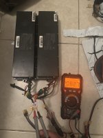
looking for a solution for setup with multiple battery packs in series and parallel

Jacoblv

1 µW
Joined
Mar 21, 2023
Messages
3
Location
Florida
A First little about my build:


About 2 years ago I bought a 2017 Hyosunge GD250R to make an e-bike/motorcycle. It home stripped out of all the wiring and mechanical parts cleaned and replaced if needed. Made a new wiring harness and after a lot of tries and failures with different motors and controllers I ended up with qs138 70h v1 and Fardriver nd72680 (great controller ) dkd display and z6 throttle. All silicon copper wires 12-16awg. Main battery wiring 0awg pure copper silicon wire with 250a 550v dc breaker.


drive train: (temporary setup )

I cut the original motor and put sprocket 520 sprockets on where the clutch was (420 chain went bad every other week and 428 didn't make much of a different ) its on first gear and connected to the original drive train ( back sprocket I changed to 52 teets instead of 46 teeth ) and put new Pirelli tires

I am planning on changing the current drive train with stanalone menual transmission to get better efficiency , torque and speed.


Since I made this build on a strict budget I had to put a lot of work into it, that way I can keep the quality of the parts high enough and not break the bank, and avoid unnecessary headachs in the future.


Next post: The battery
 

Attachments

  • IMG_3558.jpeg
    IMG_3558.jpeg
    2.9 MB · Views: 9
THE Battery:


There are some of the battery packs that made before:


Panasonic NCR18650BD 3.2ah 10A

LG INR18650MH1 3.2ah 10A

X 440 cells totalIMG_3777.jpeg
20S 22p
72v
70AH
5 KWH
220A continuous discharge
22kg


IMG_3774.jpegIMG_3844.jpegIMG_3821.jpegIMG_3820.jpeg


a 20s LFP PACK:

IMG_3524.jpeg

IMG_3525.jpegIMG_3527.jpegIMG_3528.jpegIMG_3531.jpeg

High-power Sony VTC 4 pack (great performance but short range compared to other packs in the same size )


Sony US18650VTC4 2.1AH 30A

X240

20s 12P

72v
25.2 AH
1.814 KWH
360A Continuous discharge

11kg

70619375957__14E468D2-D118-4372-BA4F-C21250B09B27.jpeg71532617120__AAB9B367-7420-499F-9C56-7DAA301A2534.jpeg71728842739__89FB3472-82BF-4987-81A2-C3D16C340E46.jpeg

Next : my current battery setup
 

Attachments

  • IMG_3858.jpeg
    IMG_3858.jpeg
    1.1 MB · Views: 6
Since getting brand new cells is way out of my budget for the size of the battery I want ,
and Getting some unknown brand cells is not a risk I am willing to take since lithium-ion can be very dangerous and it isn't worth the risk
I get my cells from the recyclers in a percentage of a price of the same cell brand new .


I was looking for a while for a scooter or ev packs in a reasonable price PER KW without the need for the dongle to activate it ( i try it before, pain in the ass . I just ended up taking them all apart, and put a dali bms).

Recently I found some packs from Bird Scooters with lg18650mh1 (on the jag35 website it is called R5 short) and I ordered 20 packs ( each 10s 4P) since they can work straight out of the box and can work in series as 72v battery pack

IMG_7541.jpegIMG_7547.jpeg


currently, I am using 10 packs each 2 pack in series for 20s configuration.

I limited the controller to 100amp line current since I am using the original battery pack on the bms and its limited to a 23amp continues .

When I got the packs I soldered each pack with xt60 connectors for discharge wires and xt30 for charging wires,
when I was testing the battery packs , and making sure they all have the same voltage and working properly before making parallel connections. The discharge wires are connected in parallel and series without an issue but the moment I connect the charging wires ,the battery pack voltage started going crazy and the bms shuts down simultaneously


So I decided to use only the discharge port to charge and discharge temporarily until I figure it out.


Currently, I am charging the packs from the discharge port and I can tell after only a few months that the packs getting out of balance, recently I had to reduce the current since I was experiencing multiple shutdowns.


I designed a case to hold 16 packs

to fit in my bike

Screenshot_20250308-081030.png
thats would provide me with enough power and range
the thing is:
I don't want to ruin the packs and I don't want to get stuck as I did many times in the past.

I was looking for a proper long term safe solution for the charging issue


I tried connecting rectifying diodes with double the amp and 1000v dc rating to each pack (I turned off regenerative brake and EABS) but without luck, the diode just overheated and started melting everything around it.after 20 min drive

I even tried to do the same with the discharge wires (diode in the opposite direction of course ). to get the charging port working properly but not much luck


I was reading about directional DC to DC to be able to run the setup that I have and I couldn't find a clear answer if that ive be ideal for my setup.


Slide192.pngbi directional convereter_1.jpeg
Of course, the obvious solution is putting one big BMS but that is WAY too much work spot-welding 16 scooter battery packs (640 cells 20s 32P) together. And I don't have insurance if the whole building gonna catch on fire 😆.
besides my last rommate called the police after he saw me spot welding a battery pack and told them i making a bomb , 🤦‍♂️ you had no idea 🤣🤣🤣🤣 i literally had to take it apart to show them what it is 😆

if anyone have an idea how to do the charging part i appaciat that

, i made a little diagram for the new battery pack wiring:


battry pack new design configurationjpg.jpeg
 
I mean the best solution is one BMS and it won't be that difficult. Connecting batteries with BMS in series is a bad idea unless the BMS are specifically designed for it. You're asking them to hold twice the voltage they are rated for which could easily be beyond what the Mosfets inside are rated for. There are a bunch of other issues with this setup but blowing up the BMS seems like one of the worst and most likely. Did you test the packs, because they could easily be all wildly different capacities being used scooter packs.

You don't need to spot weld anything to connect a BMS, you just need to open them all up, remove the old BMSs and connect the new one, leaving all the batteries welded together as they are and just soldering the small balance wires and the main positive and negative. Ideally you would also test and match them as best as possible and include larger parallel connections between each cell group than just little balance wires.
 
While the DC-DC can theoretically work, the impedance of it vs that of a battery will affect your controller's operation, especially if you are using regen or have any situation in which the motor ever generates a voltage while the controller isn't able to damp it--this can damage the controller or even destroy it if hte voltage exceeds that of any part of the controller that's across the battery bus.


Seriesing batteries with BMSes in them requires the BMSes have parts (FETs, etc) that can handle the worst-case full-system-voltage, including any regen or other motor-generated-voltages under any conditions the system might ever experience.

Otherwise, if any pack turns off because of whatever internal condition, the FETs are an open circuit with the full voltage of the system across them. If that ever for any reason exceeds what the FEts can take, they can fail, and usualy fail short circuit. That means that the BMS could then never turn the output off regardless of what happens inside the pack, so cells can then be damaged because the BMS can't protect them.

It's a silent failure, in that you won't have any obvious sign that the FEts have failed, since the packs work, unless you test specifically for the BMS being able to turn off for conditions it should (which is nto a normal part of charging, use, maintenance, etc).

You can install diodes alongside the packs to help prevent this problem; see Fechter's posts about this around the forum; I think there are diagrams, etc.

But the best solution is a single BMS that monitors all the paralelled cells in all the packs at the same time.

Next best solution is a single BMS for each seriesed pair of packs.

(both of those solutions would be replacing the BMSes originally in the packs).

There's no need to spotweld anything. If hte packs all go in one big containment unit anyway, you can simply run the wires that went from cells to original BMS to the next paralleled pack's cells, and the next, and so on, and hten the last one connects to the new BMS. If the wires aren't long enough you can solder new wires to the points the originals were connected to on the cell groups, replacing the shorter ones.
 
Last edited:
Back
Top