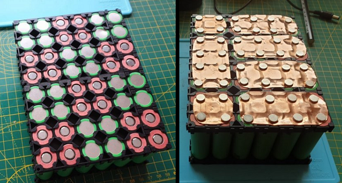
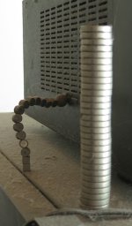
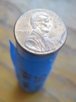
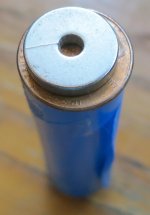
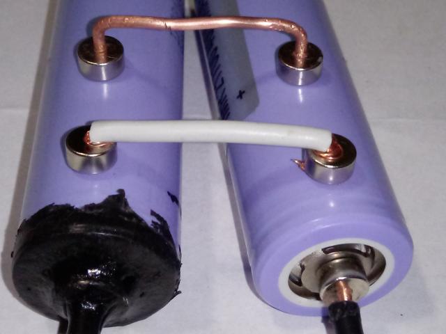
Magnets holding copper bus onto cell, no-weld no-solder

okay, im far from an expert but from what I can tell 1c is 2.5 amps
5p at 50 amps is 10 amps per cell or 4c so you need atleast 15 amp fuse wire. 1 nickelstrip is rated at 7 amps. if you pull more amps than that resistance goes up and volt sag is crazy.

Spinning Magnets is the person to ask. I just opened one of my packs with 7volt sag at 50 amps its 4p only 1 layer nickelstrip so 28 amps but on one side there were only 3 strips for the series connections. im going to solder 4-16g copper to all series connectors.
 
Hickbeard said:
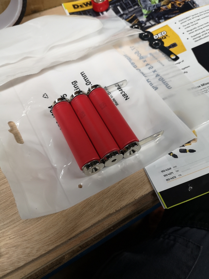
Got some magnets in.

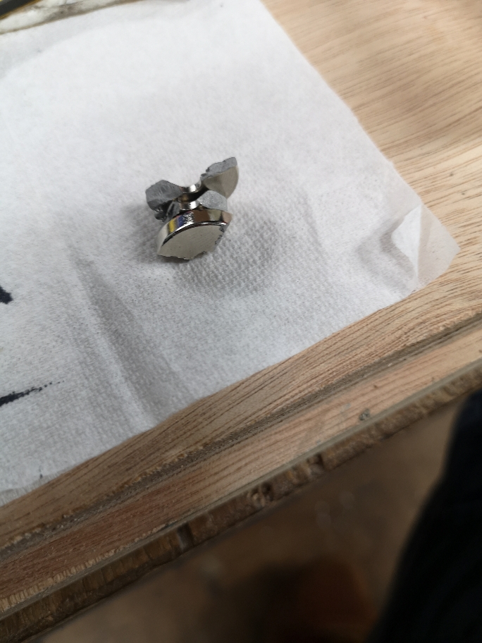
Soo... These little buggers are proper strong. But not strong enough to solely rely on.

And I've already broken one so 9 now which sucks for a 5p trial lol.

It's quite hard to keep them central though.

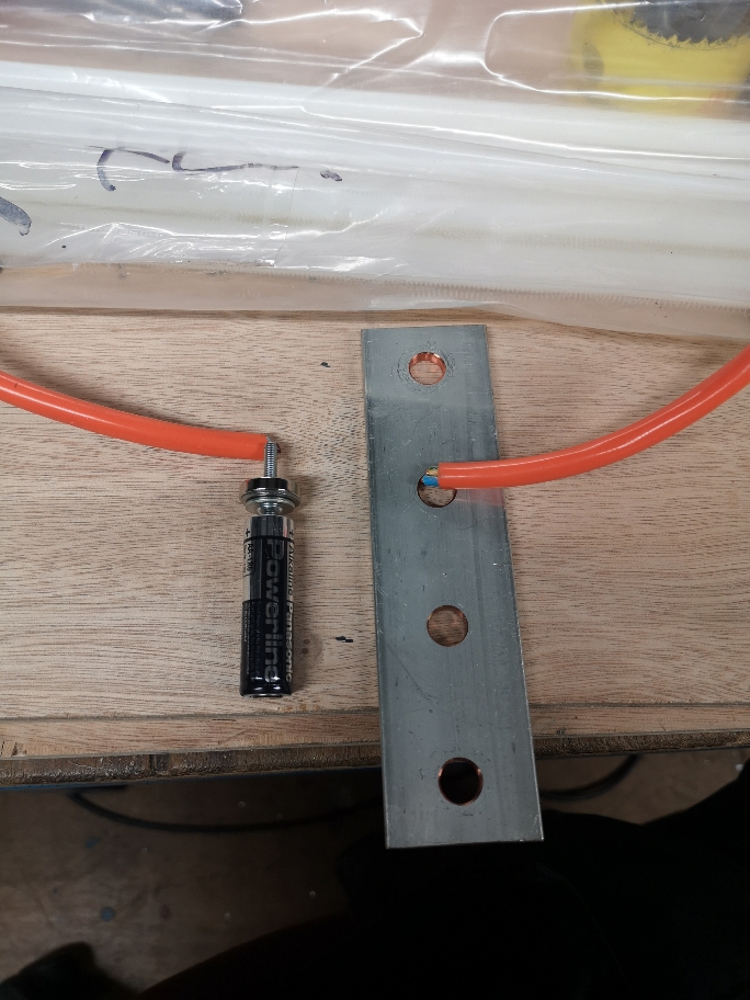
Could you solder a fuse onto a brass screw, screwed into a copper plate attached to the cell?
ee28f3580984d2c61a9ae06180e63425.jpg
af6059958b61c98fe8309f6339241b3e.jpg


Sent from my CLT-L09 using Tapatalk

you want a flat top screw for contact surface area. I don't know how many amps a brass screw can flow in terms of resistance. I wasn't invisioning using that bus strip, it cancels out the fusing because theyre parallel connected. if you cant find a copper screw a roofing or hardware store might have a 16 gauge copper flat top nail. think a copper nail for hanging a picture or copper flashing.

a roofer posted earlier in the thread maybe ask him
 
look at the thread, My Battery Builds.

its in this section, battery technology and about 20? threads below this thread. he says what fusewire he uses and what amp it blows at
 
goatman said:
you want a flat top screw for contact surface area. I don't know how many amps a brass screw can flow in terms of resistance. I wasn't invisioning using that bus strip, it cancels out the fusing because theyre parallel connected. if you cant find a copper screw a roofing or hardware store might have a 16 gauge copper flat top nail. think a copper nail for hanging a picture or copper flashing.

a roofer posted earlier in the thread maybe ask him

Yeah wouldn't use these tabs with fuses. Just showing the magnets attached.

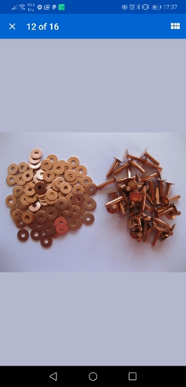
I'll just order some copper screws countersunk screws in.

Also going to order some cell holders in to hold magnet in place.

A friend of mine who is electrical/electronics trained. Said there's no point fusing each cell. Just each parallel group!

I'll check out your build thread now

Sent from my CLT-L09 using Tapatalk

 
I did a post on just parallel fusing, not series fusing. and Sam and Amberwolfe straightened out my thinking. if you are going to fuse, fuse each cell

if you are fusing to a bus bar, the bus bar is your parallel connection, basically if you are fusing to a bus bar and parallel connecting your pgroup you are double paralleling, twice the material twice the labour, kind of defeating the purpose of fusing the pack by doing twice the work just to screw up what was good

if 1 cell in your p group goes bad it will take the rest of the group with it. instead of 1 cell going bad you would have 5 cells go bad and if that happens you wont be going anywhere, the packs dead.
single cell fusing if 1 cells goes bad you only lose the ah of that cell and your battery still works and you only replace 1 cell not 5 cells
 
Yeah makes complete sense to me. Not sure where my mate was coming from.


Sent from my CLT-L09 using Tapatalk

 
Hickbeard said:
Reading through this thread (not finished yet)

https://r.tapatalk.com/shareLink/topic?url=https%3A%2F%2Fendless-sphere%2Ecom%2Fforums%2Fviewtopic%2Ephp%3Ft%3D88039&share_tid=88039&share_fid=55725&share_type=t&link_source=app

If the max current of the system is 50a. I'd need to divide tht 50a by the number of cells.

So a 14s5p pack has 70 cells. 50/70=0.7a

So a 1a fuse would give a little headroom

The max current would be dictated by the controller right? So a 50a controller. Is tht 50a max or continuous?


Sent from my CLT-L09 using Tapatalk

I looked up c rate formula. amps divided by ah is the c-rate. a 25r is 20 amp 2.5ah so 8c, a 30q is 15amp 3.0ah so 5c.

so fuse it for the continuous discharge amp rate of the cell.

14s5p at 50 amps is 10 amps per cell of the p group/5p not all 70 cells at 1 amp
 
goatman said:
Hickbeard said:
Got some magnets in.

Soo... These little buggers are proper strong. But not strong enough to solely rely on.

And I've already broken one so 9 now which sucks for a 5p trial lol.

It's quite hard to keep them central though.

Could you solder a fuse onto a brass screw, screwed into a copper plate attached to the cell?
ee28f3580984d2c61a9ae06180e63425.jpg
af6059958b61c98fe8309f6339241b3e.jpg


Sent from my CLT-L09 using Tapatalk

you want a flat top screw for contact surface area. I don't know how many amps a brass screw can flow in terms of resistance. I wasn't invisioning using that bus strip, it cancels out the fusing because theyre parallel connected. if you cant find a copper screw a roofing or hardware store might have a 16 gauge copper flat top nail. think a copper nail for hanging a picture or copper flashing.

a roofer posted earlier in the thread maybe ask him
Not following what ya doing? Looking for copper nails?
Go here:
https://www.mcmaster.com/nails
Click on Material ✔ Copper

Not seeing any copper screws at McMaster-Carr. Got lots of brass screws.
Brass pan head screws are corrosion resistant in wet environments, nonmagnetic, and electrically conductive. Length is measured from under the head.
 
In principle this.

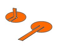
The magnet holds a copper disc with a wick that goes through the magnet to the cell.

A fuse wire attached from the wick to a bus bar.

A copper tack would probably work.
822d226348fcba2c1a6b58a574b587ea.jpg


Sent from my CLT-L09 using Tapatalk

 
spinningmagnets said:
This subject came up in another thread, and I have moved it to its own thread, due to the renewed interest....

Original thread found here: http://endless-sphere.com/forums/viewtopic.php?f=3&t=104395

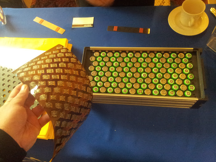
Although metal magnets conduct electricity, they have high resistance, so I would experiment with magnets over a copper strip. meaning that the copper strip is touching the cell-end. I think the copper should be thick enough to have a high current capability, but thin enough to still be flexible.

14S / 8P

20120328_132021.jpg


below, 12S / 4P (magnets held in place with super-glue, rubber-foam compression blanket, and hard side-plate)

BatteryMagnet3.png

https://amfmagnets.com/media/catalog/product/cache/1/image/250x250/9df78eab33525d08d6e5fb8d27136e95/2/3/23023.jpg

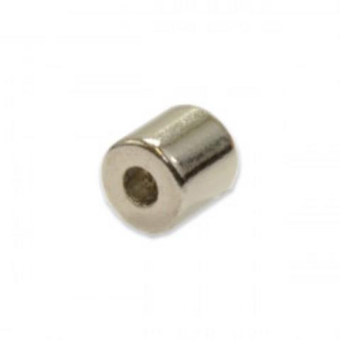
I don't know how to move the picture here but 5mmx2mmx5mm magnet. the hole is 2mm, I think 14 gauge copper is 2mm and if not it will be close enough to glue in or freeze the copper to shrink and insert. so a copper electrode basically and theyre cheap

https://amfmagnets.com/media/catalog/product/cache/1/image/250x250/9df78eab33525d08d6e5fb8d27136e95/2/3/23023.jpg
 
found these magnets but 5lb pull, the other one in previous post is only 1.5lb? pull. ill order some to see how they work

https://www.magnet4less.com/rare-earth-magnets-1-4-in-od-x-1-8-in-id-x-1-4-in-neodymium-ring-n42

https://www.magnet4less.com/images/products/ring_0.25x0.125x0.25.jpg
 
goatman said:
found these magnets but 5lb pull, the other one in previous post is only 1.5lb? pull. ill order some to see how they work

Don't fool yourself.
The stated pull requires a certain thickness of opposite iron to meet specifications.
There is free magnetic pull calculators online where you can enter the data and get the real pull force.
 
I don't think im fooling myself, the magnets have a nickel/copper/nickel coating, insert copper electrode so a fuse can be soldered from the magnet to a bus bar.

if you look at the above magnetic battery build those magnets are in something like silicone and squished between two panels. SM said magnets have high resistance. this gets rid of the high resistance.

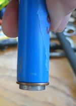
if I look at the positive button of the 18650 I think its 8mm od and the neg id is about 13mm and the button is about 1mm higher than the outer neg ring.

5mm magnet is cheaper and lighter than the other magnet and it doesn't need to be insulated from the negative and you can still use cell holders. I like to play around so ill probably plasti dip them to the cell to lock them in place. plasti dip insulates and it also grabs onto what its coating and shrinks tight and the best part is it just peels clean right off with a little bit of effort if it doesn't work. I also don't need to buy 100 or 200 to try it out, I only need to do 1 of the p groups. be nice to find the same magnet but only 3mm high or 1/8 high.
 
Honk said:
goatman said:
found these magnets but 5lb pull, the other one in previous post is only 1.5lb? pull. ill order some to see how they work

Don't fool yourself.
The stated pull requires a certain thickness of opposite iron to meet specifications.
There is free magnetic pull calculators online where you can enter the data and get the real pull force.
Cool I'll take a look.

Mine are rated at 6kg. So will check what I'll actually get

Sent from my CLT-L09 using Tapatalk

 
Hickbeard said:
Honk said:
goatman said:
found these magnets but 5lb pull, the other one in previous post is only 1.5lb? pull. ill order some to see how they work

Don't fool yourself.
The stated pull requires a certain thickness of opposite iron to meet specifications.
There is free magnetic pull calculators online where you can enter the data and get the real pull force.
Cool I'll take a look.

Mine are rated at 6kg. So will check what I'll actually get

Sent from my CLT-L09 using Tapatalk

It looks like the cannister and button thickness of my 29E is about 0.5mm max (perhaps thinner).
That is the value to enter as back iron with no return loop (open air magnetic circuit).

If I remember correctly the iron thickness should be at least 25% of the magnets thickness to avoid field saturation though the iron.
When saturated the stated pull force is not achived.
 
Interesting idea

A test is worth a thousand opinions (fechter) and it looks like someone is getting to the testing :bigthumb:

I can say that I have come across magnets that are strong beyond belief. Plenty strong to hold up thru shock and vibration if the steel used in the cans has a high enough iron content. Obviously, the closer that steel is to stainless, the less viable the idea is.

The best source for extreme magnets is old hard drives*

Other than that, I have purchased strong magnets thru specialty websites. They come with a warning about your heart and you have to sign a waver before they will ship them :confused:

I think that ANYTHING which focus on the upcoming glut of pull-down can cells is MAJOR. Cans in every size. . . and they will be everywhere. Early on they will not be binned (so will require care or a really good BMS) but later every joe will have a "binner" to characterize pull down cans into a class or category.

...

Springs
Magnets
Rubber bands. . .

The first generation of Zero Motorcycles had Emoli's held together with rubber bands (literally)

Sitting on my shelf are Amazon battery holders
2 flavors
1 is spring-loaded

I use the spring loaded, but then I am powering things that draw 300uA

good luck

-methods
 
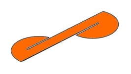
I like the button magnets with a hole in the center because that gives me a place to run a flat-head screw through it. However the idea of securing the magnet with superglue to a backing plate leaves the hole for other options, such as running a fuse-wire, as suggested earlier by others. I did a quick drawing (I cut some 0.25mm copper foil with scissors, but I can't find my camera right now) to show one option for those who might be interested in this. Someone mentioned ordering copper nails (which do exist), but I think this would be cheaper, and quite able to handle high amps.

Again, the positive end of an 18650 is quite robust (welding/soldering, etc), but my concern has always been about heat at the negative end, which provides a broad and flat surface for a magnet to hold onto in a fairly secure manner.

CopperBusMagnet1.jpg

CopperBusMagnet5.jpg
 
Some quick neodymium thoughts from my past experiments with magnetism. (And yes, they have been collecting dust. :oops: :lol: )
1: Neodymium is brittle and can easily brake.
2: As strong magnets they attract to each other quite powerfully.
3: They come in all sorts of shapes and powers.
4: The strong ones can pinch your skin off if two of them suddenly snap together. (And yes I have shed blood a couple of times having been pinched.)
5:N52 Neodymium is easily strong enough to hold even something as thick as 1¢ to a cell.


My feeling about building a magnet connector batter pack is that it is a very doable project if the builder can keep the magnets from jumping around while the pack is on a bike and moving. Something like a 3D printed holder would help, or an adhesive that would hold the magnets in place. Or both. Or, depending on the design some sort of separator like thick fish-paper or abs strips to keep the magnets apart.

Edit: Now that I think about it, copper wire connectors could even work.


Neo1.JPG
Neo2.JPG
neo3.JPG
neo4.JPG
neo5.JPG
copper wire connectors.PNG

:D :bolt:
 
e-beach said:
Some quick neodymium thoughts from my past experiments with magnetism. (And yes, they have been collecting dust. :oops: [emoji38] )
1: Neodymium is brittle and can easily brake.
2: As strong magnets they attract to each other quite powerfully.
3: They come in all sorts of shapes and powers.
4: The strong ones can pinch your skin off if two of them suddenly snap together. (And yes I have shed blood a couple of times having been pinched.)
5:N52 Neodymium is easily strong enough to hold even something as thick as 1¢ to a cell.


My feeling about building a magnet connector batter pack is that it is a very doable project if the builder can keep the magnets from jumping around while the pack is on a bike and moving. Something like a 3D printed holder would help, or an adhesive that would hold the magnets in place. Or both. Or, depending on the design some sort of separator like thick fish-paper or abs strips to keep the magnets apart.

Edit: Now that I think about it, copper wire connectors could even work.


View attachment 5
View attachment 4
View attachment 3
View attachment 2
View attachment 1


:D :bolt:

Yep I can say I've experience with 1, 2 & 4[emoji23] bloody painful

Sent from my CLT-L09 using Tapatalk

 
Just ordered some of these and some cell holders. So will have a play with these. Need to order some scrappy 18650s as I've started putting mine into my agnisium holders.
f7af4a423da4baf73d558c3dce99dd03.jpg


Sent from my CLT-L09 using Tapatalk

 
for members that are in Canada, Lee Valley Tools have these magnets. they even have the little ring magnet I was hoping for, 1/4wide x 1/16hole x 1/8 thick, out of stock till april.3 but they have a 3/8wide x 1/8hole x 1/8 high so im going to go get some of those.

I like spinning magnets idea of cutting the copper sheet the way he did, the button top isn't exactly flat, a little convex, Honk mentioned the magnet needs iron and the button has only has so much mass, the lighter and smaller the magnet would be more likely to stay in place than a stronger and heavier magnet. 3/8 is 9.5mm button top is 8mm but it has 3 legs/more iron to grab onto.
 
Has anybody actually built a whole pack & roadtested? I'm going to be building a pack soon and this process looks great, I'm just concerned that all the posts died off

EDIT
@goatman, I just found your post with further updates, great info!
https://endless-sphere.com/forums/viewtopic.php?f=14&t=106190&hilit=magnets
 
I would be hesitant to use a magnet as an electrical conductor in the circuit, they have high resistance, and if they get got, they will start losing their magnetism.

Copper is cheap and available, an excellent conductor. If reasonably thick, it would not get hot under the load of one cell, so...I remain a fan of a magnet holding a copper sheet onto the negative end.

I do encourage others to continue experimenting. If using ring magnets with a chamfered hole, the magnets can be loosely restrained onto a semi-rigid cover with a steel screw, to prevent them from wandering.

I would also recommend nickel-plated copper strip as the bus, to avoid corrosion.
 
Back
Top