
You are using an out of date browser. It may not display this or other websites correctly.
You should upgrade or use an alternative browser.
You should upgrade or use an alternative browser.
Maytag's GT gets a BMC
- Thread starter maytag
- Start date
TylerDurden
100 GW
Hi Maytag,
Great pix!
Can we get a shot of the Milwaukee BMS FETs? The heatsink clips should unscrew easily to show the part numbers on Each FET.
Thanx!

Great pix!
Can we get a shot of the Milwaukee BMS FETs? The heatsink clips should unscrew easily to show the part numbers on Each FET.
Thanx!
Looks great so far!
I don't know what's up with that. I would take it easy at first and keep a close eye on motor temp. The rating might be based on some other controller.
If the cops think you're running too much power, just point to the sticker
maytag said:Lets take a closer look at that sticker.... "250W@36v" WHAT THE HECK???
I don't know what's up with that. I would take it easy at first and keep a close eye on motor temp. The rating might be based on some other controller.
If the cops think you're running too much power, just point to the sticker
xyster
10 MW
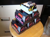
Sweet Pyramid of Emoli's, those are some drool-inducing batteries! Thanks for the pics
YO
Nice pictures, dont worry about the 250W rating, they put that sticker on them just to get them out of China, I have factory data on these I can send you where they have tested them to 700W all stock wiring with no problems at all so you should be ok.
Keep em coming, I am going to be testing one with the upgraded controller so look out for that, the motor didn't get too hot, although it is hard to tell as the coils are on the inside.
Good luck
Knoxie
maytag
100 W
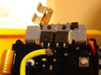
Close up of the FETs, both are IRF4104s
TylerDurden said:Can we get a shot of the Milwaukee BMS FETs? The heatsink clips should unscrew easily to show the part numbers on Each FET.
Thanx!
Attachments
TylerDurden
100 GW
You da man...
The BMS looks almost identical to the Ridgid BMS: The Ridgid also has nine traces on the ribbon, but I dont think they are all used... The MilW heatsink is also notched to accept the connector tabs.
So, if you are keeping the packs intact, the issue of a FET opening might apply here too, when the packs are in series.
What's the McGyver plan on the charging and pack construction?
Thanks again...
Tyler, I've been running my milwaukees 2s2p on the go hub and 1s6p on the cyclone without any problems at all. If your fets are the same, maybe it's ok just to hook your batteries 2s2p too. It's a lot easier than messing around with a dc-dc converter.
Reid Welch
1 MW
Agreeing with John above.
I don't see how the pack's BMS can suffer from any sort of series connection.
The pack in a string is floating. The BMS in the pack can only reference to itself. Ergo, no strain at all.
Yes? No?
I don't see how the pack's BMS can suffer from any sort of series connection.
The pack in a string is floating. The BMS in the pack can only reference to itself. Ergo, no strain at all.
Yes? No?
TylerDurden
100 GW
jondoh said:Tyler, I've been running my milwaukees 2s2p on the go hub and 1s6p on the cyclone without any problems at all. If your fets are the same, maybe it's ok just to hook your batteries 2s2p too. It's a lot easier than messing around with a dc-dc converter.
Boy Howdy.
The tricky part is what happens if an FET opens... since it hasn't happened to anybody yet, nobody knows the results.
His Fechcellency suggests that if current is kept under control, all will be well, but if the BMS cuts-off a pack for any reason an FET might see the total series voltage (?)
When sombody like the Fechtmeister gets a nagging question lurking in the background, I prefer to explore the issue before I wind-up with smoked goods. Failure-mode-analysis is ok... but on the company's budget, hopefully not mine.
:?
xyster
10 MW
Somebody at the Old V smoked a couple DeWalt BMS's after wiring the packs together (don't recall if it was series or parallel) -- and so he tapped in underneath to prevent it from happening again.
maytag
100 W
Here's a pic of my McGyver plan but it's laid out for this Filipino McGyver to understand, it's pretty simple tho. I will not be keeping the packs intact, customizing into the triangle of my frame. I will keep 2 of the packs together and still wired to its own bms(minus the plastic casings). I will build 2 packs in parallel (less bms's) then parallel these packs to 1 of the v28s still intact including parallleling the single bms connections, should act as a 7s3p pack. Same thing goes for the 2nd v28 pack left intact. Charging will be done thru the bms to keep things balanced and from overcharging. I have one charger for each bank. For ebike use I will bypass the bms thru a fuse and monitor the total pack voltage with a DrainBrain. I might possibly use the bms during ebike use to operate a LowVoltage warning LED, shouldnt be too difficult because the bms pretty much opens the circuit to the batteries when LVC is reached. Each v28 shipped uncharged, showing a reading of less than 1v thru the bms but direct connection to the batteries read about 26.9v and each cell maintains a balance of 3.83-3.84v. So knowing this I'd feel safe monitoring the total pack voltage until it gets down to around 54v (no load). Well, at least it all makes sense to me I guess.
TylerDurden said:What's the McGyver plan on the charging and pack construction?
Thanks again...
Reid Welch
1 MW
Aha. Now I see, I learn by you guys.
Herr Aflaschcindernose
10 µW
Wvat dese tings need den so dey don't be trippen upTylerDurden said:...The tricky part is what happens if an FET opens...
is wvat der Horze has alwvayz hat:
FETLOCKS
H A
fetlock ( ) n. A projection on the lower part of the leg of a horse or related animal, above and behind the hoof.
maytag
100 W
here's another pic of the custom build plan with the 2 packs left intact just for a better understanding. When I first discussed this plan with Jondoh, he thought there was no way I'm going to make it all fit in the GTs tiny triangle. John, looks like its all going to fit with a little room to spare once the stock v28 battery connectors are removed
TylerDurden
100 GW
maytag said:I will build 2 packs in parallel (less bms's) then parallel these packs to 1 of the v28s still intact including paralleling the single bms connections, should act as a 7s3p pack. Same thing goes for the 2nd v28 pack left intact. Charging will be done thru the bms to keep things balanced and from overcharging. I have one charger for each bank.
Do I understand correctly, that you will run the monitoring leads from each BMS (which usually go to a single cell) to three cells (the original, plus the two parallel cells)?
maytag
100 W
Yes, thats the concept. Fechter mentioned something similar could be done with the batteryspace lipos and their bms pcb at the same time I was thinking this up for the v28 packs. I think if all the cells are closely matched everything should work out nicely. The RC guys who have been using these cells for some time now dont even use a bms for run times and they only use cell balancers once every 5-10 charges. I've read numerous RC posts about how well the emoli cells stay balanced. I'm easily convinced since I've cracked open 3 of my Milwaukee v28 packs and the individual cell measurements all fall between 3.82v-3.84v. We'll soon find out, I've got about $800 riding on this concept. Stay tuned.
TylerDurden said:maytag said:I will build 2 packs in parallel (less bms's) then parallel these packs to 1 of the v28s still intact including paralleling the single bms connections, should act as a 7s3p pack. Same thing goes for the 2nd v28 pack left intact. Charging will be done thru the bms to keep things balanced and from overcharging. I have one charger for each bank.
Do I understand correctly, that you will run the monitoring leads from each BMS (which usually go to a single cell) to three cells (the original, plus the two parallel cells)?

maytag
100 W
John, thanks for leading me to him. Great guy, planning on doing more business with him. Hopefully I get the GT on the road soon so I can join you and Ric on those ebike rides.
jondoh said:wow! that's a tight fit. Can't wait to see the finished product!
I'm glad things worked out with chuck. A good man he is.
TylerDurden
100 GW
Sorry if I'm being a pest...
If the cells in your small 3p sub-packs get out of balance, how will you equalize them?
This is a whole new concept here... intriguing.
8)
If the cells in your small 3p sub-packs get out of balance, how will you equalize them?
This is a whole new concept here... intriguing.
8)
maytag
100 W
the 3p sub packs will constantly be connected to the bms. I dont know much about the Milwaukee bms but if it does not keep the cells balanced during discharge, I"m almost sure it will balance during charging. Its all an idea, gonna have to wait for the final outcome. If it doesnt turn out how I planned I can always use the RC Lithium chargers and balancers if need be.
TylerDurden said:Sorry if I'm being a pest...
If the cells in your small 3p sub-packs get out of balance, how will you equalize them?
This is a whole new concept here... intriguing.
8)
TylerDurden
100 GW
Here's my concern:
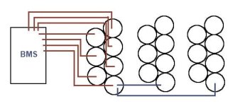
If you have only one lead monitoring 3 cells, they can get out of balance.
Each sub-pack of 3 cells will show an average voltage, and the BMS can't really know what any individual cell is doing.
It will let a cell go too high or too low, since it can only see the average of the three its sensing.
So, its not really gonna be able to do what it is designed to do.
(only one 3p shown for illustration, all cells would have leads.)
Attachments
xyster
10 MW
Each sub-pack of 3 cells will show an average voltage, and the BMS can't really know what any individual cell is doing.
It will let a cell go too high or too low, since it can only see the average of the three its sensing.
Like lead, cells of all lithium chemistries balance themselves when wired in parallel. This is how each one of the 300 cells in my pack gets balanced using *only*
20 chargers.In other words, given a very short time for the voltage (and charge state) to equilibrate, each cell in a parallel subpack of three cells (or in my case, 15 cells) will have the same voltage if you disconnected and individually tested.
If I'm understanding Maytag's plan correctly, it should work.
Yes, he needs to run the bms wires to all the cells. Sort of a buddy pair system. The bms will 'see' the correct number of cells, but each cell will be 3 in parallel. Each 3-cell sub pack is wired in parallel, so the voltage on all 3 cells will be the same.
TylerDurden
100 GW
Yeah, I think that's where I'm snagged.
The packs would need to be 3p7s to balance, not 7s3p...
The packs would need to be 3p7s to balance, not 7s3p...
Similar threads
- Replies
- 0
- Views
- 3,351
- Replies
- 9
- Views
- 1,718
- Replies
- 31
- Views
- 23,193
- Replies
- 5
- Views
- 3,160