
You are using an out of date browser. It may not display this or other websites correctly.
You should upgrade or use an alternative browser.
You should upgrade or use an alternative browser.
Maytag's GT gets a BMC
- Thread starter maytag
- Start date
Reid Welch
1 MW
Yet, in Xyster's (well-working) pack,
because there is no discharge monitoring,
when his pack ages or if a cell goes substantially off in capacity,
and they may not lose capacity all at the same rate,
then it's during the discharge phase that trouble would show up--
eventually one cell will fail and reverse, even though pack-overall-voltage
seems normal....
I apologize if my newbieness is showing.
But here's a toast to full monitoring of every cell with warning afforded or shut-down of that series string, at least, in the case of the demise of the weakest sister.
It is for this reason of wildly complex wirings that the simple big-cell lipoly pack premise appeals to myself at present.
Perhaps I'm not thinking sufficiently enough on practical, real-life long-term results from a pack.
pardon ramble,
r.
TylerDurden
100 GW
Ok, looking good here...
The Emoli chemistry is much more fault-tolerant that Xyster's LiPo, so this looks very do-able; and since it is only 3p, there will be less "masking" of a lame cell.

The Emoli chemistry is much more fault-tolerant that Xyster's LiPo, so this looks very do-able; and since it is only 3p, there will be less "masking" of a lame cell.
xyster
10 MW
Yet, in Xyster's (well-working) pack,
because there is no discharge monitoring,
when his pack ages or if a cell goes substantially off in capacity,
and they may not lose capacity all at the same rate,
then it's during the discharge phase that trouble would show up--
eventually one cell will fail and reverse, even though pack-overall-voltage
seems normal....
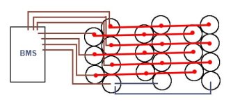
You raise a valid concern I've considered too. But, due to lithium manufacturing homogeneity as discussed at battery university, unlike nickel batteries, one lithium cell is unlikely to age faster and suddenly puke and die than any other. They all age at the same, predicable rate, their capacity slowly disappearing over the years until finally they can't go as far as we need them to go anymore. Some of my subpacks are about 6 months older than others. I can tell because the voltage on those older subpacks declines a little bit faster than the newer. In addition to the full-time voltmeter on my handlebars monitoring the whole-pack voltage, for long rides I bring my DVM and measure one of these low packs through its charge port. At this time, the weakest subpacks at 50% discharge are about 0.02 volts less than the newer subpacks. Since they age at the same rate, I expect this small spread to remain about the same.
My next little project is to also mount a digital voltmeter to the handlebars for monitoring only the weakest subpack. So when I'm out on the road I'll see something like:
Voltmeter A: 76 volts (3.8 volt/subpack average)
Voltmeter B: 3.78 volts
I'll know to stop when Voltmeter B reads 3.70 volts.
Reid Welch
1 MW
8) Well thought out. Thanks.
xyster runs a right ship--not a bike
xyster runs a right ship--not a bike
maytag
100 W
maytag
100 W

maytag
100 W

maytag
100 W

maytag
100 W

maytag
100 W
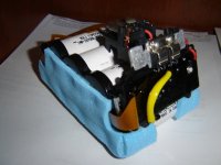
And after about 8hrs of labor this is what I end up with. I probablly still have another 2hrs left to solder on the new busbars and to complete the wiring.
TylerDurden
100 GW
I probablly still have another 2hrs left to solder on the new busbars and to complete the wiring.
Yeah, that's what I always say too...
...4hrs later, I look up at the clock and say: "Oh-well, it has to get done."
Then I take four motrin for my stiff neck.
:lol:
xyster
10 MW
I probablly still have another 2hrs left to solder on the new busbars and to complete the wiring.
Oh Waaah.... I had to resolder my entire formerly 225 cell pack cuz I ruptured a couple cells. I've spent over 40 total hours soldering the darn thing. And at least another 100 completing the rest of the bike. This looks to be going very smoothly in comparison.
Nice work
Thats a great idea and a cheap way to get a nice high capacity pack with good quality cells, looking keenly on to see how this goes, its they way forward boys with both you and xyster showing those lead lovers there are other options :lol: keep it up you guys!!
I also get my dosage of lipo of course, been out on the KMX today, that is going so well in the spring heat!! thats going to get 48V 20AH 18lbs of lipo, should take me to 40mph with my taller gearing and 50-60 mile range on a nice still day!!
Cheers
Knoxie
maytag
100 W
You aint kidding, 6 more hours and i was only able to finish up one of the banks although I was watching golf while working on the pack.
TylerDurden said:I probablly still have another 2hrs left to solder on the new busbars and to complete the wiring.
Yeah, that's what I always say too...
...4hrs later, I look up at the clock and say: "Oh-well, it has to get done."
Then I take four motrin for my stiff neck.
:lol:
Attachments

maytag
100 W
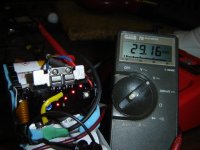
To answer the question about if my charging scheme is going to work, worked like a charm. I finished up one of the banks (3p7s) so thought it was a good time to put it through the charging test. Here's the before and after shots.
BEFORE - individual cells = 3.83v
BEFORE - individual cells = 3.83v
maytag
100 W
Ypedal
100 TW
Nice work !!!.. very interesting !
What wttage iron did you use ? how long do you estimate it took per solder joint ? Do these cells get warm/hot during use, do yo uplan to vent the box in any way ? or just seal it watertight ?
What wttage iron did you use ? how long do you estimate it took per solder joint ? Do these cells get warm/hot during use, do yo uplan to vent the box in any way ? or just seal it watertight ?
maytag
100 W
I remember seeing some brass strips at our local hobby shop back when I was into RC boats and trucks and I think I remember my bro (Joystix) building some nicad packs with these. This is my first ever building a battery pack of any sort.
D-Man said:Nice work. Where did you get the battery busbars at?
maytag
100 W
I'm using a 40watt adjustable Weller Solder station(set to 4, 5 is max) with a medium tip shaped like a phillips screwdriver. What seems to take a lot of the time is cutting the busbars to length. I use a dremel with cutting wheel and after cutting each busbar I turn the dremel's rpms down to lightly scuff up each location on the busbar where it will make contact to each cell. I scuffed up both ends of each cell as well before building the pack. Before soldering the busbar onto the cells I tin each cell, tinning is really quick (1-2sec per cell). All this preping speeds up the actual soldering job so I wont have to hold the iron on the cells for very long. Estimating the time for each solder joint is probably around 10-15sec of the iron actually touching each cell in 3 passes. 1st pass to tin the cells, 2nd to tack the bar in place and 3rd to complete the solder joint. I'm sure these cells put out some heat during operation, not sure about how much heat but its probably a good thing for any battery pack to have some type of ventilation. I dont ride in the rain and the weather in Cali is almost always ideal so venting the box wont be a problem.
Nearly 20 years ago I started out in the Electronics field as a bench tech so I've had a few years of experience soldering day-in and day-out. But for the past 15yrs my job involves absolutely zero soldering so the only thing keeping my soldering skills decent are mine and my bro's EV projects. Personally I think the soldering job I did on the first battery bank is a little shabby and I believe its because I'm now 39 and I cant seem to keep my hands from shaking. :{
Nearly 20 years ago I started out in the Electronics field as a bench tech so I've had a few years of experience soldering day-in and day-out. But for the past 15yrs my job involves absolutely zero soldering so the only thing keeping my soldering skills decent are mine and my bro's EV projects. Personally I think the soldering job I did on the first battery bank is a little shabby and I believe its because I'm now 39 and I cant seem to keep my hands from shaking. :{
Ypedal said:Nice work !!!.. very interesting !
What wttage iron did you use ? how long do you estimate it took per solder joint ? Do these cells get warm/hot during use, do yo uplan to vent the box in any way ? or just seal it watertight ?
maytag
100 W
Ran into a major problem with the 2nd battery bank and there's a lesson to be learned if anyone decides to follow my footsteps. Just because the pack is brand new and was shipped in an uncharged state (~0v coming out of the bms side) its a good idea to throw it on the charger to make sure it can complete a full charge cycle. I kept one v28 pack intact for each battery bank and just trusted it was in good working order. It just so happened that the pack chosed for this bank had a bad bms. It was about 12:30am, after 3hrs of soldering up the busbars and balancing leads the plan was to leave it on the backyard porch charging while I get some shuteye. Darn thing wouldnt start the charge process. I spent a good hour troubleshooting and contemplating what the hell was I going to do. I was just about to call it a night and put an order for another v28 in the morning but suddenly I wasnt tired and I had 4 other bms's that were torn apart from the other packs. I decided to dig out the silicone around where the ribbon cable feeds into one of the bms's to see if I can make this work, might as well try before dumping another $100 into a 7th v28 pack. By the time I was done it was 4:30am and was able to solder in part of a hard drive ribbon cable to salvage the pack. Here are some photos.
Attachments

maytag
100 W
maytag
100 W
Soldering the busbars and balancing leads went an hour smoother than the 1st battery bank. I think the solder joints turned out much better this time around. It was all coming around nicely until I ran into the brick wall.
maytag
100 W
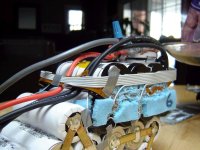
Here's a shot of the 2 battery banks connected in series for a total pack voltage of 57.5v. The first battery bank had individual balanced cell voltages of 4.16v straight off the charger. Now that its been sitting for several days they've come down 4.10v per cell. The 2nd battery bank has the cells balanced at 4.12v off the charger, I dont know if its just the characteristics of each individual bms for the .04v difference or if there were any losses from using the hard drive ribbon cable. Hey I'm just happy that its all working. Still looking for a source who sells large enough heat shrink tubing that can fit the individual banks, anyone know of any? Hoping to get the 1st test ride by the weekend.
Similar threads
- Replies
- 0
- Views
- 3,357
- Replies
- 9
- Views
- 1,720
- Replies
- 31
- Views
- 23,201
- Replies
- 5
- Views
- 3,161