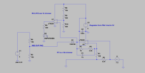
Meanwell NES Schematic..almost complete

Hi SBD

I can't comment on your schematic or the idea at all, but am wondering why you would want to do it when Cor has found a way to easily mod the NES via a much simpler approach. It just seems like re inventing the wheel with something more complicated..using extra external circuitry when a simple potentiometer will do the job..
Or is there something more to your board that will allow extra functionality. I am not knocking what you have done, just wondered what advantage doing something like that has over the R134 pot mod

Neil
 
Hi Neil,

I'm not trying to reinvent the wheel just make is spin a bit faster :D .

My motivation here is to find the easiest way get configurable current limiting with minimal tapping into the PSU internals.
If I use a 5V external regulator driven from the PSU output voltage I think I can get current limiting with only one wire going to the OVP pad (very easy task for all DIY enthusiasts like me).

I'm willing to take on the task of the PCB layout and I will be more than happy to publish the Gerber files and BOM for all to use.

I added another op amp in a comparator configuration that will show when the current falls below 3% of MAX current to indicate end of charge.
Here are the current schematics:

Current Limiter w End of Charge LED.png

S.B.D
 
S.B.D said:
Hi Neil,

I'm not trying to reinvent the wheel just make is spin a bit faster :D .

My motivation here is to find the easiest way get configurable current limiting with minimal tapping into the PSU internals.

OK, yes I see why you are trying to do it, and see where you are coming from with less tapping to the PSU internals, but to my mind at least, having to build and test a board, is greater complexity and less easy than just soldering two wires to the board, and maybe cutting one trace. Building up a complete board is far more work and more difficult for a complete novice. Doing one of these boards is good for someone with a bit of electronics construction experience, but I think for a complete novice, the other method is fair less likely to introduce errors ..there are two wire to go to the board, soldering to passive components, no worries about static sensitive devices, overheating IC's, transistors etc. If these boards wer to come down ready populated, and then the only work was to solder the one wire to the OVP point, then yes, even easier, but for someone new to this, having to build th board is a step to far, where jsut fitting two wires is do-able

Don't get me wrong, I use the 3 pot version of the Fetcher/Goodrum board, but for the current limiting, still mod the PSU board too, using the external board for functions that the PSU does not (yet ) have mods for. Those extra functions being, current monitoring and charge 'shutdown' once the current drops below pre set level
 
S.B.D said:
Hi Neil,
I'm not trying to reinvent the wheel just make is spin a bit faster :D .
My motivation here is to find the easiest way get configurable current limiting with minimal tapping into the PSU internals.
If I use a 5V external regulator driven from the PSU output voltage I think I can get current limiting with only one wire going to the OVP pad (very easy task for all DIY enthusiasts like me).
Hi SBD,
But you *did* re-invent most of the 3-pot current limiter, only configured the parts a little different, but the basic operation is the same.
The only thing missing is a switch to "float" once the second opamp detects that current has fallen to somewhere in the 1A or below region, whatever set with the pot represented by R9 and R10.
One word of warning: most regulators have a 35V absolute max rating, so you can't use them on a 48V supply, for that reason Richard added a zener when you are running from a 36V or higher supply, to drop some voltage away in the zener before reaching the regulator.
BTW, there is a symbol for a potmeter that looks like a resistor with a tap from the side, that will allow you to avoid the double resistor and explanatory text around R7 and R9+R10. Note that R7 says 10 Ohm at this moment, your comment has the correct value of 10k. (or 5k will also work).
 
Hi,

I don't think I ever mentioned I invented anything and have never seen the circuit you are talking about. I can just be proud of the fact that my circuit is very similar as you say ( I am not sure how many ways you can go with external current limiting). My hobby is electronics and I build as much things on my own as time permits ( ebike speed controllers and rc plane electronics). I love doing things hands on. My first circuit too many years ago was an inverter driving an LED. This has probably been done before but I still was very much proud of myself and learned a lot from it.

Going back to the circuit.... I could not find a potentiometer on the LTspice sim.
What do you propose to float the battery? A MOSFET or a relay? I hate relays...

Thanks
S.B.D
 
Here is the 3 pot version referred to

file.php


There was also a single pot version

file.php


the thread about them is here:
http://endless-sphere.com/forums/viewtopic.php?f=31&t=21768&start=135
 
Hi Neil,

Thanks for the link.
Looking at the schematics I see the main difference between the circuits.
Mine uses the op amp in linear mode as opposed to open loop ("comparator mode").
Can't this cause a large output voltage ripple and maybe instability as the comparator has only two output states? I guess the bandwidth of the comparator is the answer.
Has someone looked at the output voltage with an oscilloscope (not an RMS digital multimeter), I would love to know the answer..

Why is the third "float Pot" needed? Is is used to allow a larger output voltage change than the stock pot?

Thanks,
S.B.D
 
S.B.D said:
Why is the third "float Pot" needed? Is is used to allow a larger output voltage change than the stock pot?
No idea with regard to the first question, but the third pot is the one that controlls the 'float voltage'
This three pot design, has current limiting adjustable as per the single pot design.

The board then monitors the output current as the charge progresses, and due to the battery becoming charged and its voltage rsisign to meet that of the charger, the current flow drops.
The second pot sets the threshold current where the board kicks the PSU from charge mode in to a lower voltage 'float mode'
All float mode is, is the board lowering the output voltage of the charger to a little below that of the battery, and changing the bi-colour LED rom Orange to Green.
The second pot, sets the current threshold when this change over occurs. Seem to remember from about 1 amp and below. So the board monitors current, and when it drops below the value set by the second pot, the LED changes colour and float mode 'kicks in'

It is the third pot that controls the amount the PSU drops its voltage by.
So in practice, you break the 'Float enable ' jumper, set the PSU via its own on board pot, to the voltage you require for your fully charged battery.

You then install the Float Enable Jumper. This (with no battery connected) kicks the board in to float mode. This pulls the output voltage of the charger down. the amount it pulls down is determined by the third pot. Range is only a volt or two, but enough to stop the charge current flowing to the battery.
 
Hay dudes.
Got my Meanwell NES-350-36 in the mail today.

Upper adjustable voltage is 41.06v.
Lower adjustable voltage is 30.76v.
Unmodified amp output: 11.30A.

Not totally ideal for charging 10S RC Lipo ( needs at least 41.5v ), but it will work.

Thank god for the schematic. The shunt was hiding underneath a giant glob of goo near the output caps. At first glance i thought that i had some bizarre board that had no shunt.

So; I plan on doing the shunt shave method yet again, as i did with my S-350-48.

Now i have a question for you guys:

I do plan on using the constant fan ON modification. However i would like to power a small intake fan up front off the 12v rail. The fan will draw 0.1A. Would this work without any complications?
 
neptronix said:
Hay dudes.
Got my Meanwell NES-350-36 in the mail today.

Upper adjustable voltage is 41.06v.
Lower adjustable voltage is 30.76v.
Unmodified amp output: 11.30A.

Not totally ideal for charging 10S RC Lipo ( needs at least 41.5v ), but it will work.

Thank god for the schematic. The shunt was hiding underneath a giant glob of goo near the output caps. At first glance i thought that i had some bizarre board that had no shunt.

So; I plan on doing the shunt shave method yet again, as i did with my S-350-48.

Now i have a question for you guys:

I do plan on using the constant fan ON modification. However i would like to power a small intake fan up front off the 12v rail. The fan will draw 0.1A. Would this work without any complications?

Hey Dave, why not do the R134 mod to limit current- you could use a varistor and adjust current easily? I haven't looked at my pcb- maybe it's a real pita to get to?

As for the fan- couldn't tell you. I'll leave that to someone smarter than me. You could try it while the unit is on and see if it alters the output voltage?
 
I did the fan mod, works!

Did the shunt mod too, but now it screeches :(
I always liked the shunt mod idea because i felt it was the least invasive, electronically.

The installed shunt is very sensitive.. not sure what it is made out of, but taking a chunk out of it and bridging it with solder didn't help - that took the amps from 11.3a to 13.5a!!. Ended up using two tiny copper strands as a replacement, after trying 7 strands.

Current is not stable with the copper strands however, it appears to fluctuate and go down slowly.
I think this is because the copper heats up, and the resistance rises, perhaps?

I may have to dump this shunt mod idea after all. The screeching is a bad sign.

OT: here is a meanwell press release about the NES models.. http://www.meanwell.com/news/H2010142.html
 
neptronix said:
Thank god for the schematic. The shunt was hiding underneath a giant glob of goo near the output caps. At first glance i thought that i had some bizarre board that had no shunt.
Hi neptronix, I am certainly not God but the idea of reverse engineering the NES schematic was exactly this - to be able to mod it and have an idea what you are doing to the supply, so you can make an assumption of the result...
neptronix said:
So; I plan on doing the shunt shave method yet again, as i did with my S-350-48.
The way the supply is designed, the small voltage of the Shunt is amplified with an opamp and that feeds into the Voltage feedback of the PWM controller. Even a small ripple or some noise on the current measurement will lead to the PWM controller not gradually throttling back, but to random skipped cycles. You describe a screeching sound and I think that is what might be the effect of noise on the current limit feedback.
I cannot guarantee that modding R134 will have any other effect though. It may be necessary to remove the noise from the current feedback by limiting the bandwidth of the opamp and/or filtering the output. Unfortunately that may lead to instability if done wrong. I do not know what will happen without trying.
Note that the current measurement across the shunt is not supposed to come on normally as that limit is above the max power of the supply, so it may be that MeanWell simply did not pay much attention to the operation in continuous current limit and accepted the screeching when reaching the limit.
neptronix said:
Now i have a question for you guys:
I do plan on using the constant fan ON modification. However i would like to power a small intake fan up front off the 12v rail. The fan will draw 0.1A. Would this work without any complications?
The 12V is taken off the main transformer with a small winding and passes through a linear regulator. I am not sure how much voltage the regulator drops but the weird situation may arise that adding more load drops the voltage before the regulator enough that the power dissipated in the regulator actually reduces under the higher load. You will know if you measure what happens when doing this.
 
Neil,
I tried to power up your supply with only one switching transistor (the other parallel one died and shorted in your experiments) and with a diode that I found in an old supply I have here.
Unfortunately that diode may not have been high enough voltage as it shorted, the last switching transistor died and the fuse blew. Sounds exactly like what happened to you in your last experiment.
OK, I need to get a pair of the original transistors and a fully compatible diode and try again...
I want to build a small BMS as well, so I may order everything from Mouser or so, instead of scrounging around in Frys.
 
Well, good luck.

That other supply ( Pro Peak ) that I was tracing...well I may have had some luck..though yet to try it out.

I was in a store the other day when I was in England, and they had some of the Pro Peak supplies n the shelf. I asked if the chap knew anything about them and if they failed, was there a usual cause. he sad yes, he did know them, and it wa usually a ballast resistor. Now I have some resistors that seem to be very high in value..300 ohm or more when they are marked as 2 ohm. They are quarter watt resistors on the base of the first pair of transistors. I have some 5w 2R2 resistors here, so will try replacing them with these and see what happens.
 
Anyone any idea on how to increase the max voltage of the unit? Mine tops out @ 57.5v but I'd like to be able to set 62.25v as I'm playing with 15s Lipo now.
 
Check out the schematic and the string of zener diodes ZD51 and 52

I believe they need changing if you want to go higher...You may also need to alter the values of capacitors, if the main output caps are only 63 volt..you my want to change them for 100v too.

Not sure if there are any other mods...Cor will be the bloke who will tell us.

You may also need to change the pot that you use to alter the voltage...SVR1 from memory..probably 1k now...maybe need to change it to 5k
 
Basically up a creek without a paddle w/ this 36v 350w meanwell.

If nobody has tried the current resistor mod, i'm not going to mangle it further since i don't know what i'm doing - i'm not an EE or anything close to it.

Has anyone successfully current limited it and used it as a charger?
 
are you meaning the NES one?
\
guess we will have to wait to see what Cor comes up with
 
I mean the NES one, yeah...

anyone want to buy it, so i can get a BMSBattery 'alloy shell' type charger? :(
 
I would hang on to it.

Even if you did get an alloy shell charger, you could pop the Meanwell in series with it if you ever needed higher voltage..using the Alloy shell charger as the current limit
 
You probably want to start looking out for some of the bigger PSU's that get supplied with all sorts of things..PC monitors, PC's etc...anything, jsut get hold of a whole rack of them and open them up..If you get them for nothing from the local dump/garage sale /yard sales etc.

Open them up, power them up and twist the pots and see what happens. You will eventually find one that you can limit the current on..OK so you may fry and few..but so what..I have a box of old one s like that, that I fried by tinkering.
Stick the dead ones in another box for use for scrap parts...caps, resistors, heatsinks etc
Even try PC supplies..the internal ones. Do a google on which wires to connect together, or check back through some of my PC PSU posts.

Or just bite the bullet and do the mod on the Menawell that Cor found
 
I've been running shunt modded NES-350-48 for months now - pumps out 7.7amps on a 12s pack. Yes it screeches a bit (particulary at the start of the charge) but it's still going strong. I estimate it's done 50 charges and 75 hours of run time.
 
Thank you for chipping in, amigafan.
I thought screeching was a sign that magic smoke was to be released fairly soon.

Does yours hold a steady current ..?
 
Sigh.
I gave the shunt mod another shot.
Fan mod is now on/off swich. Doesn't seem to increase the current level, like the older meanwells.

Threw some solder on it.. then it went back to 13A output. No screeching, pretty stable current, but started heating up fairly quick.
Shaved it a bit. 10.5A-11.75A and rather unstable current level, according to the Turnigy watt meter. Then screeching.

Fan mod doesn't affect the screeching.
Lowering the voltage from 41.5v on the 36v unit down to 40v doesn't affect the screeching.

Amigafan, is your current unstable as well?
 
Back
Top