neptronix said:
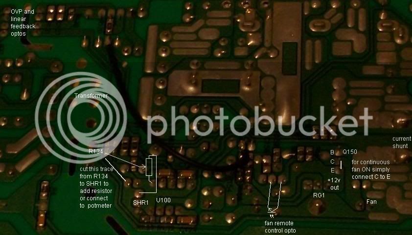
What really confused me was the 'r134' right next to the arrow, indicating that the drawing of what looks like a resistor was r134.
I can see that looks weird,. Maybe the points Cor has shown the resistor connected to are just other points on the board, that are common electrically to where it (R143) needs to go, and it is just that not actually putting it 'either side' of the cut trace makes it seem odd
neptronix said:
Also i don't understand why there is a line coming from the transformer straight to the shr1.. or why a line coming from the transformer straight to anything is there. it made me nervous to even go there. I thought maybe the resistor went there but i was confused.
Think that black wire is there merely because Cor's board is mine that I zapped, doing an earlier mod. I could not repair it so passed it on to Cor. I think this black wire is something to do with either his mods to get it to work, or possibly a broken trace on the board , that was 'fixed' at the factory like that in order to make it work.
neptronix said:
For the resistor mod, going off what he wrote, it sounded like you took the value of r134 and increased it by 1K to get a 25% reduction in current.
Exactly.. go from his drawing and compare to your board
http://i1236.photobucket.com/albums/ff455/cor_van_de_water/Currentcontrolschematic.jpg
neptronix said:
That's why i'm wondering if i run the resistor in parallel or series ( in series you have to cut the trace though, right? )
Series with R134, so cut the trace and put the new resistor across the cut at two convenient points.
neptronix said:
Maybe i should PM cor just to be 100% sure?
Can't harm. although as he had said previously he is busy..and if he is not hear responding, it is usually because he is snowed under with other stuff
neptronix said:
for the shunt mod, i adjusted the length of the copper and the amount of the solder on it to be approximately the same value as the original. Anything less than the original value makes it screech like crazy. Anything more than the original value produces the same amount of current as the original, which is really weird. The shunts must work very differently here.
Cant remember..but only one shunt right? small change in that is going to make big difference. it is only in the milli Ohm range anyway, so cutting or adding to it can make a big difference.
I am thinking that since you have done a shunt mod, and although managed to rectify it to somewhere near normal,you may need to experiment with different values of additional resistors to get your current where you want it. Maybe the pot mod might be better.
No more replies for a few hrs now.
have started playing with dd-wrt firmware hacks to routers..trying to make a wireless bridge and antenna setup to span 500 meter of field to get wifi from house to workshop, so off to do that now.
Good luck...PS if it goes wrong..send it to Cor to give him another to experiment with like I did
")