Micro Lebowski Controller - DIY 3kw

Well, with 100A sensors and 120A setting,
The chips dials up the voltage until it sees 120A, but it will never reach that as the sensors only go to 100A. So the chip keeps pilling up the voltage. Doesn't matter the current reaches 200A or so, the sensor says we've not reached 120A yet so more voltage !
 
Lebowski said:
Well, with 100A sensors and 120A setting,
The chips dials up the voltage until it sees 120A, but it will never reach that as the sensors only go to 100A. So the chip keeps pilling up the voltage. Doesn't matter the current reaches 200A or so, the sensor says we've not reached 120A yet so more voltage !
When I was originally testing on the YSR you said the chip would sense this and konk out.?
 
conk out or explode. c'mon where's the difference?! ;)
i learned better to stay on the safe side. and it was my fault to no think about it. this controller is for techies anyway. too many options that can be set wrong and make it selfdestruct. but better than too many "are you sure?" "really" questions.
 
the whole issue is my head all the time, so i tried to reconstruct what happened. i sent HUNDREDS of mails to lebowski (thanks for your support!!!) and can't remember what led to what, and what settings/tests work and which not. i wish i was a more methodical guy. i totally am NOT. :( so not writing down my findings to be able to follow my doings. well, probably this is why i spam these threads and write mails to keep track of my thoughts.

so it suddenly flashed in my head, and i went through my mails: the situation the FET exploded was one of those "not correctly configured" controller situations. i flashed a 0xFFFF file to reset all to default, went through all testing, and when you do that, the "FOC measurement" settings for current are EXTREME. like a few THOUSAND amps, where it should be 20-40A (in my case). i forgot to set this to reasonable values. so this made the FET explode. could be that this also made the wires to the caps melt because of the EXTREME current flowing for a few ms.

i guess this is a reasonable explanation. what do you think?

why the LTC3638 just gave up? i don't know. this happened during testing, BEFORE the FET problem. but it first showed up after testing lebowski's "extreme" .hex files with some error current checking disabled, which is asked him for. i guess this is a valueable information now. i would vote AGAINST those settings. and it makes sense to me now. somehow the dc/dc converter was destroyed during that. and this also was the reason why FOC measurement etc didn't work correctly afterwards. if the chip's supply voltage drops below a certain treshold even for milliseconds it resets. you won't notice that with a DMM.

any comment really welcome. i'm confident now, that with new parts, and going through regular setup, everything is safe to use. can't wait to try andy's new design :)
 
izeman said:
conk out or explode. c'mon where's the difference?! ;)
i learned better to stay on the safe side. and it was my fault to no think about it. this controller is for techies anyway. too many options that can be set wrong and make it selfdestruct. but better than too many "are you sure?" "really" questions.
Reason I ask is we rely on the system and our math to be what determines the max current or in the ICs case max mv th IC sees in a pull power run.

One little mistake on calculations or having a voltage supply drop a touch that feeds the current sensor and you have an un-detected over current.
 
izeman said:
the whole issue is my head all the time, so i tried to reconstruct what happened. i sent HUNDREDS of mails to lebowski (thanks for your support!!!) and can't remember what led to what, and what settings/tests work and which not. i wish i was a more methodical guy. i totally am NOT. :( so not writing down my findings to be able to follow my doings. well, probably this is why i spam these threads and write mails to keep track of my thoughts.

so it suddenly flashed in my head, and i went through my mails: the situation the FET exploded was one of those "not correctly configured" controller situations. i flashed a 0xFFFF file to reset all to default, went through all testing, and when you do that, the "FOC measurement" settings for current are EXTREME. like a few THOUSAND amps, where it should be 20-40A (in my case). i forgot to set this to reasonable values. so this made the FET explode. could be that this also made the wires to the caps melt because of the EXTREME current flowing for a few ms.

i guess this is a reasonable explanation. what do you think?

why the LTC3638 just gave up? i don't know. this happened during testing, BEFORE the FET problem. but it first showed up after testing lebowski's "extreme" .hex files with some error current checking disabled, which is asked him for. i guess this is a valueable information now. i would vote AGAINST those settings. and it makes sense to me now. somehow the dc/dc converter was destroyed during that. and this also was the reason why FOC measurement etc didn't work correctly afterwards. if the chip's supply voltage drops below a certain treshold even for milliseconds it resets. you won't notice that with a DMM.

any comment really welcome. i'm confident now, that with new parts, and going through regular setup, everything is safe to use. can't wait to try andy's new design :)
Been there....

With a properly set up Desat circuit you will never blow up any more mosfets.
 
Lebowski said:
Desat will be included in v3.00 :D

But I don't see how it will prevent blowup due to setting current values higher than what the sensors are made for...
You might be able to over heat a mosfet without tripping desat.

If you try to run to much current thought a mosfet the desat trips and it shuts it down while still in safe limits of the mosfets operation.

If the mosfet heats up it will have a lower desat trip point....


The desat has saved me over 1000 blown IGBTs with 470v applied to them!!!
 
i guess there would be no way to prevent what happened to me. i had foc testing current set to dozen the times of what the fet was made for. so i demanded it to blow. ;)
and this was not sensor related. i'm quite sure that setting current to more than what the sensors are rated for did cause any issues.
 
hey all.... So V2now lives.. and having built it I am keen for V3...

I've got a couple of ideas for the power bus, to make assembly easier. I think the order in which I put it together will make a BIG DIFFERENCE...

Also, I've been looking into lower cost components because it's unlikely I will need to run at 140V, and therefore a 140V input with 15V and 5V output DCDC powersupply is somewhat unnecessary, but it was good to build one just to prove I can! and that it works..

[youtube]8J1dvZI8hk4[/youtube]

Izeman - your boards are in the mail. There are a couple of things that I have done differently from how it is marked on the circuit boards to make the assembly easier. I'll email you directly with info.

Some Photos... to come...
 
here goes my 4000th post, a little update on andy's v2 controller.
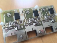
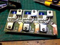
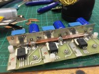
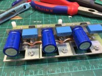
andy was so kind to send me his new FET and controller board. the cpu board can be reused from v1. lebowski was so kind to send me a new CPU with v2.80 installed, as my old cpu somehow was partly damaged after a deadly configuration of phase current (set to some hundred amps for a single 4468. my fault). this destroyed the CAPs and somehow had some impact on the cpu.

so with fresh parts, and 150A current sensors instead of the 100A ones and new bigger caps (220u instead of 100u) i started building v2. here are some pics. the power lines where reinforced with 5mm2 copper rod and phase connection got some 1mm thick copper plates as well (6mm wide, so 6mm2 cross section).

i hope to be ready for a test run this evening or tomorrow. keep your fingers crossed :)

Foto 06.08.16, 13 44 25.jpg

Foto 07.08.16, 12 03 57.jpg

Foto 07.08.16, 12 35 26.jpg

Foto 07.08.16, 12 57 03.jpg
 
andy you say the controller is aimed at 3kW.
i installed 150A current sensors, and the 4468 FETs have a 190A current limit (260A silicone), so they should be capable of 150A phase? would you vote against that?
lebowski recommended to add a temp sensor. which ones should i use? and is there a way to fly-wire connect them to the cpu board i have?
 
It uses a digital sensor, the type is shown in the build your own thread (after 4 years i still dont know how to do links on this the worst android tablet ever)...

By the way, if the battery can handle it you can crank up the battery current to about 85% of the phase current, then the controller will never be limited by battery current. You'll be up to 5 kW then, almost as much as my little Honda 110i (6 kw) which does 90kmh...
 
What really is the relationship between battery and phase current? Is there an advantage in increasing the battery current to 85% as you suggest? Obviously it's more power, but in.terms of the phase current what's actually happening in the controller?
 
izeman said:
andy you say the controller is aimed at 3kW.
i installed 150A current sensors, and the 4468 FETs have a 190A current limit (260A silicone), so they should be capable of 150A phase? would you vote against that?
lebowski recommended to add a temp sensor. which ones should i use? and is there a way to fly-wire connect them to the cpu board i have?


I have 4468s in my controller and I run 150amps phase, I even increased phase current to 200amps for a couple of rides and it didn't blow up
but I have backed it down to 150amps phase again.
 
Animalector said:
What really is the relationship between battery and phase current? Is there an advantage in increasing the battery current to 85% as you suggest? Obviously it's more power, but in.terms of the phase current what's actually happening in the controller?

If I remember correctly the battery current can be calculated from the phase current:

I_battery = 0.85 * Vout_real[%] * I_phase

with Vout_real[%] the output sine wave amplitude as a part of the maximum the controller can deliver. If you look at part of a parameter save from Izeman:
Code:
throttle:                  99 %
wanted_i_torque:           88.4 A
Vout_real:                 66 %
with 100A max phase current and full throttle you would expect 100A wanted_i_torque, but it has been reduced to 88.4A due to the 50A battery current limit Izeman has set.

I do not see the point of limiting the battery current except for when the battery cannot deliver, or to limit total power.
 
hmmm. very interesting comments. thanks.

I do not see the point of limiting the battery current except for when the battery cannot deliver, or to limit total power.

my battery is a 20Ah 12s lipo, which should be able to do 100-200A without any problems. but if i up the battery current to let's say 100A, then the motor will see 50V * 100A = 5kW. but i i not capable of 5kW. it will overheat in no time.

so if i ride uphill for a longer time i need to reduce the maximum power that goes to the motor. i'd like to keep it between 2.000W and 2.500W max. would reducing the PHASE current only acchieve that?

if it would work, this is still no solution. i need PHASE CURRENT to get the bike rolling. the more the better :) so reducing phase is not an option.

how would i set these two parameter best to acchive optimal performance from a stand-stil, that will not exceed 2.500W?
 
izeman said:
hmmm. very interesting comments. thanks.

I do not see the point of limiting the battery current except for when the battery cannot deliver, or to limit total power.

my battery is a 20Ah 12s lipo, which should be able to do 100-200A without any problems. but if i up the battery current to let's say 100A, then the motor will see 50V * 100A = 5kW. but i i not capable of 5kW. it will overheat in no time.

so if i ride uphill for a longer time i need to reduce the maximum power that goes to the motor. i'd like to keep it between 2.000W and 2.500W max. would reducing the PHASE current only acchieve that?

if it would work, this is still no solution. i need PHASE CURRENT to get the bike rolling. the more the better :) so reducing phase is not an option.

how would i set these two parameter best to acchive optimal performance from a stand-stil, that will not exceed 2.500W?

I think the motor cares only for the amount of self-heating, which comes from the phase current and is independent from battery current. Whether high phase current happens at high or low motor speed doesn't really matter for the heating of the motor I think (this is what makes self heating independent from battery current).

Best performance from standstill, or in any type of case, put in as much phase current as the motor can take. This will heat up the motor very quickly, therefore you need to install a temperature sensors monitoring the motor coils temperature. The phase current will then be automatically reduced as the motor heats up. The typically available torque in an average situation will not be as high as the max due to the on average warm motor. But, before the motor gets hot, the high phase current allowed for a cold motor will give you maximum torque.
 
looking at an ICE by the way, a ratio of 1:3.5 between battery current : phase current seems reasonable.

For the electric motor 1:3.5 will work out to a 1:3 ratio of available torque at high speed versus low speed.

An ICE has a certain amount of torque which, with the typical gearbox where the ratio between highest and lowest gear is 1:3, results in a 1:3 ratio of high speed : low speed torque.
 
So if.the current sensor is 150A and the Fets can handle 150A, why not.set battery current to 150A ( if battery can deliver). Therefore why do most controllers have a battery to phase ratio multiplier?
 
Animalector said:
So if.the current sensor is 150A and the Fets can handle 150A, why not.set battery current to 150A ( if battery can deliver). Therefore why do most controllers have a battery to phase ratio multiplier?

The battery to phase multiplication happens naturally due to motor inductance and is a marketing gimmick..
Controller with the same battery as phase current will feel weak at low speed as we are used to having more torque
at low speed than at high speed. Also, I think the mainstream battery cannot deliver so much current (as much as the
wanted phase current), we at ES are a special bunch with our high-grade LiPo's . And finally, when you can always
sustain a high phase current you will need temp sensors in both the motor and the controller.
 
Back
Top