Micro Lebowski Controller - DIY 3kw

this weekend I'll puit it on my list of things to do to hook up my controller and do a FOC measurement hook up a CRO and measure the 5V rail...see what happens? yeah?

Just because it's on my list doesn't mean it'll get done.

Andy
 
good news. now i tested with a 4s nimh battery discharged to 5.15v unloaded. it sags to 4.9v with 0.3a load (tested with my icharger)
now PWM works perfectly nice :) i tested with 2x 12v 100w light bulbs and set test duty to 25% and 50%.
this give the correct voltages at the phase wires in relation to the battery voltage.
so i can confirm that the 5v dc/dc converter may need to be set to 5.2v so it works maybe, or i need a more stable 5v source.
the 5v rail of the controller was somehow not appropriate before, or was dying already during the previous tests. under certain conditions i was unable to do FOC measurement (lebowski you remember?), i'm sure it will work now.
any idea where i could get a stable dc/dc converter?
 
mistery resets, I've always traced those to the 5V. Same when the controller doesn't appear to switch on: fault was the chip powering up, 5V dipping, chip resetting and powering up again, again 5V dipping etc etc
 
Lebowski said:
mistery resets, I've always traced those to the 5V. Same when the controller doesn't appear to switch on: fault was the chip powering up, 5V dipping, chip resetting and powering up again, again 5V dipping etc etc
so do you have a good idea for a stable 5v supply? 7805?
 
izeman said:
Lebowski said:
mistery resets, I've always traced those to the 5V. Same when the controller doesn't appear to switch on: fault was the chip powering up, 5V dipping, chip resetting and powering up again, again 5V dipping etc etc
so do you have a good idea for a stable 5v supply? 7805?

Just the controller Ic alone takes 200mA from the 5V (add to that current sensors, hall sensors, throttle etc) so if a 7805 takes 15V in then you easily have 2W dissipation in there. Too much.

Based on my experiences with my own PCB, I think the best solution for the 5V is to use a DCDC converter that takes the 15V as its input. And use lots of caps.
 
Lebowski said:
Just the controller Ic alone takes 200mA from the 5V (add to that current sensors, hall sensors, throttle etc) so if a 7805 takes 15V in then you easily have 2W dissipation in there. Too much.
the LTC3638 used by andy is just 250mA. http://www.linear.com/product/LTC3638
so couldn't this be a major issue at all?

Based on my experiences with my own PCB, I think the best solution for the 5V is to use a DCDC converter that takes the 15V as its input. And use lots of caps.
adding another voltage regulator to the 15v - generated by a LTC3638 as well will make thinks worse on the 15v line, won't it? so we would need a complete new dc/dc circuit. generating a stable powerfull 15v voltage which then can easily be converted to 5v. correct?
OR: i can take a lot a 1.2v nimh cells with me to power the controller externally *lol*

edit: another solution: put them in parallel: "A feedback comparator output enables multiple LTC3638s to be connected in parallel for higher current applications.". but they are already quite expensive :(
 
wouldn't something like a LM1575 for 5v work? http://www.produktinfo.conrad.com/datenblaetter/1000000-1099999/001013714-da-01-en-IC_REG_B_LM2575HVT_5_0_NOPB_TO_220_5_TID.pdf
they are not very efficient at low current. this is between 65% and 75%. but if we talk about 300mA load this will be 200mA*5v heat. correct? this is 1W, and can be easily handled when you mount the regulator on the controller case.

edit: MAX17502FATB+ seems much better http://www.produktinfo.conrad.com/datenblaetter/1100000-1199999/001124204-da-01-en-IC_REG_ABWAE_MAX17502FATB_T_WFDFN_10_MAX.pdf
 
to sum up what happened: now after i used another dc/dc converter, it's cap just BLEW UP. got hot within seconds and exploded. so i thought the cap was bad, and replaced it with a new one 100v 10u. this blew again after a few seconds. but this time the FET on the dc/dc converter exploded as well, and the 15v dc/dc onboard converter chip exploded as well.

not looking too good. just replacing both the LTC3638, will just lead to another exploded chip.

so i was in discussion with lebowski, and he said that normally the 3 big caps (100v120u) should take care of that. i mentioned that there was no spark when i connect the battery, but this was not new, as i always used a. inrush limiter - just for bench testing it used a direct attached battery.

so i took a look at the caps and measured continuity to the board. they are attached to GND and VCC of course. but ALL 3 wires to GND where just MOLTEN. you can see it on the picture. HOW CAN THAT HAPPEN????
you can clearly see that they are molten, as the wire is thicker where it melted.

i can repair that, but w/o knowing the cause i guess this will happen again.
at least i now found the reason why the dc/dcs broke all the time.

here is a picture. exposure while taken was very high so you can see the dark part.
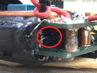
Foto 05.06.16, 17 14 10.jpg
 
Well I guess the short answer is that it was used beyond its rating ... I typically use a single 220uF cap but only for upto 30A phase (peak, not rms). The one I use is rated for I believe 1.7A ripple current, which I assume to mean 1.7A RMS. The peak current can be much higher, the RMS is what counts as this determines the cap heating (together with the caps ESR or internal series resistance). For 100A peak I would probably use 2 or 3 caps of 220uF, with a combined rating of at least 5A RMS.

I think the deciding factor for how much cap to use is actually the heating of the caps. If they heat up too much you don't have enough caps and should use more. I've never noticed heating of the (single) 220uF at 30A phase in real world conditions (on the bike).

I remember there was an issue with fake FETs at the time, maybe there's also fake caps ? I got mine from Digikey...
http://www.eevblog.com/forum/projects/warning-fake-large-electrolytic-on-ebay-!!/


P.S. about the molten wire, it almost looks as if the cap shorted out and the resulting high current blew the wire... did you measure it, is it shorted out ? Seems to me the most logical reason for the molten wire...
 
the caps were sized by andy. and he took great care afaik. those caps are not fake, and are quite expensive. ultra low ripple current if i remember correctly.
it's 3x 120u so 360u all together. this is less than the xie chang.
i measured the 3 caps and none of them seems shorted out. they measure 110,110 and 106uF.
if the caps would have overheated: wouldn't they just open the top and vent?
so the question about the molten wire still remains. ..
 
You should use POLY caps.
 
In short they have much higher current ripple rating for the size and cost wise vs all the specs you need as well as their life span they are cheaper then electrolytics they have Very Low ERL which is most important and Low ESR which is a little important.

Everything I build for power electronics is now using poly caps.

Read this thread and follow what HH says especially. https://endless-sphere.com/forums/viewtopic.php?f=30&t=31804&start=25
 
izeman said:
could it be that the wires melted when one of the FETs blew? if so i have to investigate why the FET blew. i can't remember ...
Or when you set it above the current sensor limit ? Didn't you once hear a popping sound but couldn't find anything wrong upon inspection ?
 
Lebowski said:
izeman said:
could it be that the wires melted when one of the FETs blew? if so i have to investigate why the FET blew. i can't remember ...
Or when you set it above the current sensor limit ? Didn't you once hear a popping sound but couldn't find anything wrong upon inspection ?
could very possibly be. just to repeat and write it down: i have 100A bidirectional current sensors installed. i set the phase current to 120A, which was too much for the current sensors. i don't know what voltage they sent to the controller, but i guess it couldn't have been more than 5v (which is the highest voltage possible?!).
but let's say that this event made one of the FETs pop: can this lead to all three cap's wires melt at the very same time?
i want to understand what happened here electronic wise. the big caps are between VCC and GND, and are there to level the voltage and reduce spikes coming from the low side FETs. and it was a low side FET that popped. so if during this over current situation there was a short between GND and VCC: how could that make the cap's wires melt?
sorry for the maybe dumb question. i'm no electronics engineer. i just want to be sure that when i order new CAPs, new LTCs and other stuff from farnell, that this will not happen again - or what to avoid to not make it happen again.
@arlo: i read the thread you posted, but sorry, i don't understand it. my knowledge is way below what you guys are talking there. :/
 
Arlo1 said:
You should use POLY caps.
i can't find anything that says POLY. no idea what to search for :(
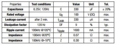
i looked for 100v 330u at my local store, and found this WÜRTH WCAP‑ATUL 860040878008, with these specs. what values (other then voltage and capacitance) are important, and what should the be? is the impedance and ripple current good?

Capture.JPG
 
Based on 30A phase working good with 1700mA ripple current caps, I would use in the order of 5A ripple current for the 100A you want... you can use 3 caps in parallel and achieve 5A

The cap you list can take 1.6A, lets say this is rms, together with the 0.07 ohm this is 0.18W of dissipation....
 
Lebowski said:
Based on 30A phase working good with 1700mA ripple current caps, I would use in the order of 5A ripple current for the 100A you want... you can use 3 caps in parallel and achieve 5A

The cap you list can take 1.6A, lets say this is rms, together with the 0.07 ohm this is 0.18W of dissipation....
the ones installed have 0,74A ripple current so, it's 2,2A for all of them. so was this sized way too small from the very beginning?
http://www.farnell.com/datasheets/1909383.pdf
i guess having too small caps won't cause any of the other issues i had with this controller, right?!
they have 0,15 Ohm each, so this would be 0,0075 Ohm for 3 in parallel, correct? they shouldn't heat at all.

edit: i almost forgot: there are also 3x 0,47u poly caps between VCC and GND. and if i understand arlo's link correctly, then those should be ideal for what we want, and you need way less capacitance than with electrolytic caps. i can't say if 3x 0,47u is enough though, but mayb together with 360u "regular" caps?
 
You always needto use both a big cap (like 220uf i use) and a small cap like 470nF. Reason is that caps have a parasitic inductance inside which prevents them from being useful above a certain frequency. This is where the smaller cap comes into play, it is good upto a much higher frequency.
I think with no caps the behavior of the complete controller becomes unpredictable. Wiring inductance to the battery and battery high frequency properties become important, things that are not supposed to be a factor. The caps are supposed to remove all those unknowns from the equation...
 
Back
Top