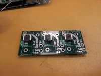
Micro Lebowski Controller - DIY 3kw

Thought I would throw this up if it is useful for this build or the next version. I started to use these self cinching nuts in PCBs a few years ago. They have worked well for me. They are a self cinching design with a serrated barrel that you press into the PCB. I typically use a very small arbor press to do it. When you get the plated hole size correct they insert easily and hold well. They are sometimes difficult to find in small quantities. They are typically zinc plated carbon steel, so conduction is not the best. Data sheet attached.
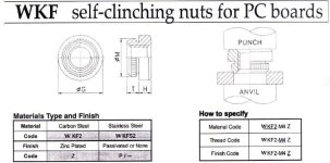
DataPix.jpg
 
Standoffs are available in many heights and can be cut, only enough height is needed to take screw threads from both sides.

Alternately a metal block can be drilled and tapped so the PCB mounting holes are offset from the FET mounting holes

Alternately rivnuts or some other captured nut could be used.

And there are other commercial products such as those bigmoose suggested (I didn't see his until after writing most of this post).

Nuts soldered to a PCB will likely fail in tension.
 
Ok.. getting there. I need to do some more testing.. I did a PWM test tonight. but I was in a rush and didn't think to set some meaningful parameters.

Ayways it pulses.. that's a start.

Soldering all the signal level interconnects between the boards is a pain. and I'm not comfortable with them. I am considering an interface layer.. with routed signal traces to provide a shield between the FETS and the driver board.. I'll post a CAD render when I have thought through the details.

pics.
View attachment 4
IMG_20150305_190755 (Custom).jpg
IMG_20150305_190747 (Custom).jpg
IMG_20150305_185611 (Custom).jpg
IMG_20150305_171912 (Custom).jpg
 
you're talking about the BLUE and BROWN wires (2x 3 pieces) that are hard to solder? i can imagine that.
aren't the thru holes on both boards superposable? so if you use short thick (eg. 4mm2) "pin header" like wires, solder those to the middle pcb and then stick all 6 of them through the FET board and solder from the outside? this should work?!
 
solder those to the middle pcb and then stick all 6 of them through the FET board and solder from the outside? this should work?!

Yes that would work... BUT...

aren't the thru holes on both boards superposable

Unfortunately not. :oops:

but I can make an interface PCB which will allow this and provide an isolation layer.. which should slot over the current sensors and won't impact overall height.. that's the hope. I'll consider this.. and see if it's practical.. but it will make assembly more reliable easier and give me a big fat ground plane between the fets and everything else.

anywyas .. test what I got before I consider further changes/ mods. :mrgreen:

Andy..
 
Yeah I do realise that. It was literally a 3 minute test. I was late for squash hadn't had dinner yet. Nobody else was in the office. But really wanted to see something on the cro.. I did. So even though I feel like an idiot for not actually setting realistic values im pretty happy there was at least something. :mrgreen: in going to call that a.... win!
 
i bought some 6mm2 solid copper wire. damn that is thin!! 6mm2 is a little bit more copper than awg10. awg10 is the wire i run from controller to motor, so i guess it should be enough for 2.5kW peak and enough for connection the two boards, as well as beefing up the pcb traces. what do you think?
it's a shame that the hole are not in the same place. but it still would not be a big task to bend the wire in the correct angle, solder it in, and then install the FET/sensor pcb. i don't think that installing a forth pcb will add reliability and make installation that much easier. after all that's v1 and you can still add that for v2 or make the holes match?!

this is a picture of 6mm2 solid wire (2,7mm diameter) compared to my index finger, which btw is not that strange ill purple color :)

Capture.JPG
 
I reckon 10mm2. Only because it Will fill the space better both should handle the current right?. You know what I think would be better... 5mm x 2mm copper bar. Rather than tube / wire.

Andy
 
Animalector said:
I reckon 10mm2. Only because it Will fill the space better both should handle the current right?. You know what I think would be better... 5mm x 2mm copper bar. Rather than tube / wire.

Andy
but the 5x2mm copper bar will not fit in the 4mm holes ;)
maybe i can find some 3x3mm for the connection between FET and ACS758 to solder to the pcb traces.
 
Animalector said:
Ahh but you can bend it at 90 degrees Top and bottom and solder it or screw it maybe. I just want threaded copper block. That's the go
screwing it through the holes is no good idea as the contact area is very small. bending the round wire to fit and and soldering it would be the best connection wise. only problem i see: you will never again be able to separate the two boards in case of maintenance/repair. you could only use a tiny saw and cut the wires in two and then remove the halves.
 
Here's an idea. How about soldering mating 4 mm bullet connectors in your 4 mm holes, then solder the gate drive wires, then snap the boards together using the bullets for structure as well as power. You'd have to be careful to ensure that all 12 connectors' axes are aligned, of course. The ones in the photo might be a little stubby but various sizes are available.

http://www.amain.com/castle-creations-6.5mm-high-current-bullet-connector-set/p34184

16710825676_6a8b9ce9c3_n.jpg
 
cycborg said:
Here's an idea. How about soldering mating 4 mm bullet connectors in your 4 mm holes, then solder the gate drive wires, then snap the boards together using the bullets for structure as well as power.
4mmm bullets will NOT be able to carry the current. or is it battery current only? it's midnight right now, and i have some glasses of wine already :) but even if it is battery current only, then 4mm bullets is maybe a bit too small?!
edit: i saw that you posted 6.5mm bullets. but how to solder them to the board? the pads are 6mm only.
 
Animalector said:
Yeah those ones are.. Its the small signal wires that aren't. .
for sure. but that's no problem. they can be longer anyway. solder them first, then make the "big" connections and hide the signal wires between the boards. no rubbing or short should happen.
 
Back
Top