Modifying (or fixing) output of cheap Luna Cycle 52V charger

Joined
Aug 8, 2016
Messages
14
Location
Milwaukee
This is how I modified a cheap charger to better suite my needs. Disclaimer: I DO not recommend doing this yourself. Also I won't dive too deep into the technical background, because Wikipedia.

I ordered a BBSHD kit last month with a Luna 52V battery, and for $30 added the lowest cost, 3Amp charger, shown here: http://lunacycle.com/batteries/chargers/standard-3amp-52v-dolphin-shark-bottle-battery-charger/
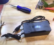
IMG_7376.JPG

This is definitely a low-cost unit but does include a fan (despite the product description). My charger happen to have a small solder ball rattling around inside that I had to pull out before operating.
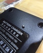
IMG_7379.JPG

With the solder ball out, I ran a full charge on the battery pack and saw the charger continued up to 59.17V, which works out to 4.23V per cell. 4.2V is the maximum cell voltage recommended by the manufacturer, and running the cells that high will severely limit the potential life. I was pretty uncomfortable being above 4.2V but didn't want to spring $100 for an adjustable charger.

I figured this was a CC/CV (constant current / constant voltage) charger that turned off at a set voltage (in this case, 59.17V, instead of the specified 58.8V ). The circuit inside is pretty straight forward but I was only interested in the DC-output side of the large isolation transformer, which is shown on the right. Note I've disconnected the fan which plugs into the white 2-pin connector.
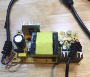
IMG_7780.JPG

The bottom of the board has surface mount components including one i.c. each that control the circuits before and after the transformer.
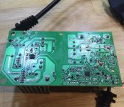
IMG_7779.JPG

I was hoping the small I.C. on the right would be some type of switching controller circuit, meaning I could look up the part number and then figure out how the output voltage was controlled. I should have expected a simpler, lower-cost design, because Instead that 8-pin chip is an LM358G, meaning a dual op-amp. I assumed each channel was set up as comparators (comparing the output voltage to a fixed value, and turning the output circuit on and off)
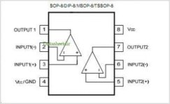
UTC-LM358-pinout.jpg

As I hoped, the outputs of this op amp each drive two cascaded transistors, where channel 1 activates the optical isolator to turn-on / turn-off the AC side of the circuit, which is how the charger is turned off at a set voltage. Channel 2 turns on the fan when the charge is operating. I focused on the inputs to channel 1 to figure out how the output voltage was being scaled and fed back into the comparator circuit. I only found one feedback trace from the charger output back to the comparator circuit, with three inline resistors that scaled the 59.17 output voltage down to 2.493V at the comparator.
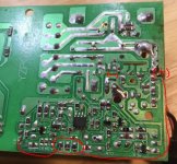
Capture.JPG

The resistors are 0K, 100K, and 4.99K, meaning a series combination of approx. 105K Ohms. I am targeting about 4.1V per cell (57.4V output). By using the ratio of the original output voltage over the current resistance, I calculated a new resistance to achieve a new output voltage,which worked out to 101.9Kohms. I have some 4.7K Ohm resistors handy, and putting one in parallel with the existing 4.99K resistor, will yield a total network of about 102.5kOhms. That's close enough for a low-tolerance circuit like this.
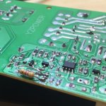
IMG_7788.JPG
Afterwards I added insulating tape to protect the newly added component and buttoned the whole thing back together. The finished mod yielded 57.8V, which should greatly extend the life of the pack.
 
Nice work, thanks for documenting that.

Lowering the charging voltage to a BMS controlled pack will prevent the BMS from fully balancing the pack and may lead to shorter pack life rather than longer. BMS's often balance at 4.15V so ideally this would be the minimum voltage that the charger would output. If you output 4.1v per cell times 14 that allows an imbalance of 0.7V to exist in the pack. Often the two cells that power the BMS will run lower voltage, and the rest of the cells higher. These low cells will hit LVC and cut off the pack early and reduce the effective capacity of the pack. The rest of the cells will then sit at 4.15V and the two low cells will never fully charge, instead distributing that 0.7V imbalance between them and eventually charging only to 3.8V.

Since these packs don't generally have individual cell group outputs we cannot manually monitor or balance them, we must depend on the BMS to do this, and the BMS depends on certain behavior of the charger to complete this task.
 
Huh. It had never occurred to me that the BMS trigger voltage would be that high, but thanks, that is good information. Even though there is a lot of tolerance built into the voltage divider circuit in the charger, the performance seems pretty stable and repeatable. I think I will install a switch so I can run a full, balancing charge every 50 or 100 miles, and a slightly lesser charge the rest of the time. To do that I will probably also remove the SMD 4.99K resistor and replace it with something that will get as close as I can to the original 58.8V target, instead of going over. It will probably take some trial and error using the 10% resistors I have on hand, but nothing beats free.
 
Nice work, and thanks for sharing!

However,, worrying much about .03v overcharge, when a bms is going to pull it back down right away. Kind of pointless IMO.

If you tuned it down to 4.1v per cell, now you just eliminated the balancing function of your bms. Which IMO, is worse than the .03v overcharge.

Install the switch makes a ton of sense. Charge to 4.23 about monthly, for a balance. Don't charge to 4.1v, till you are going to ride in the next 12 hours or so,, in other words, charge only the night before you will actually ride. Minimize the time it sits at 4.1v too, unless its winter and it's stored cool.


BTW,, the cheap chargers tend to put out less voltage later on, something the designers may have known and planned for. Or it's just close enough for that price range. :mrgreen:
 
Hmm... I've been thinking about this and it doesn't quite make sense. Here's what I've come up with:

The short answer is, it can't be that risky, if Luna sells an "80%" charger for their packs: http://lunacycle.com/batteries/chargers/luna-charger-52v-advanced-300w-ebike-charger/

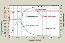
The longer answer is, I'd prefer to know exactly how the BMS operates, but I'm still fine. "Top of charge" cell balancing takes time, because you're bleeding off excess charge, and thermal limitations of the bleed resistors require the charge rate to be very low during the bleed/balance. The charger i'm using (and that Luna is selling with this pack) isn't smart enough to hold the final 58.8 voltage- it just hits it and turns off, so I'm missing the flat part of the voltage curve in this graph:
new.jpg
(From here: http://batteryuniversity.com/learn/article/charging_lithium_ion_batteries)

This means balancing needs to start earlier, which to your point, could be 4.15V. But it doesn't really matter, because the pack is still being driven to 57,8V, meaning worst case is 12*4.15 = 49.8, so 57.8 - 49.8 leaves 8Volts for the remaining two cells, so 4V per cell powering the BMS. Not ideal, but not terrible.

Now I'm motivated to pop open the battery and see:
1 - When and how much power is the BMS drawing to operate, and is it only powered from a portion of the pack (terrible design!)
2 - At what cell voltage does the BMS balance circuit switch on

As for charging over 4.2V per cell, i agree the 0.03V isn't a big deal, but I would prefer to never be above 4.1V. 100% SOC stresses the cells, so why age them faster if I don't need to. Plus, to your point, you can't be sure the cell-to-cell voltage is always perfectly uniform, and typically won't be, so a lower target creates margin for variation.
 
14*4.1 = 57.4, we didn't use the same values in the calculations.

If you can find or measure the specs for your BMS great, then you can work with that.

You can also do a survey of available BMS's to see what's typical. Batteryspace.com has specs on theirs, for some examples that you can look at. They don't talk about where power is taken from, unfortunately, but they do show balancing voltage trip points and over/undervoltage levels.
 
Robot_Exterminator said:
Hmm... I've been thinking about this and it doesn't quite make sense. Here's what I've come up with:
. The charger i'm using (and that Luna is selling with this pack) isn't smart enough to hold the final 58.8 voltage- it just hits it and turns off, so I'm missing the flat part of the voltage curve in this graph:............
:shock: Are you sure ?...i would recheck that charger operation.
If that is in fact what is happening..( no CV charge period ) , then your pack will never be fully charged, never settle at much more than 4.0v, and never be balanced !
From my testing, and also shown on your graph, cells are only at 70-75% capacity when the CC charge voltage curve tops out.
The CV stage is not just for balancing , but also to charge the remaining 25% or so of cell capacity.!
 
Hillhater said:
Robot_Exterminator said:
Hmm... I've been thinking about this and it doesn't quite make sense. Here's what I've come up with:
. The charger i'm using (and that Luna is selling with this pack) isn't smart enough to hold the final 58.8 voltage- it just hits it and turns off, so I'm missing the flat part of the voltage curve in this graph:............
:shock: Are you sure ?...i would recheck that charger operation.
If that is in fact what is happening..( no CV charge period ) , then your pack will never be fully charged, never settle at much more than 4.0v, and never be balanced !
From my testing, and also shown on your graph, cells are only at 70-75% capacity when the CC charge voltage curve tops out.
The CV stage is not just for balancing , but also to charge the remaining 25% or so of cell capacity.!

Good point Hillhater. It should hold at least until the current drops quite low, at least.
 
Agreed with all, in principle. However this charger is definitely not sophisticated enough to hold a Constant voltage charge. Once it gets to the hardware-controlled set point, it switches off.

As a side note I think people are over obsessed with charging 18650s to 100%. Unless you really need the maximum range (which I don't) it's just not worth the reduction in cell life.
 
Robot_Exterminator said:
Agreed with all, in principle. However this charger is definitely not sophisticated enough to hold a Constant voltage charge. Once it gets to the hardware-controlled set point, it switches off.
It might not be the charger--if the BMS is cutting off it's input because a cell is hitting HVC, the charger would detect no current flow and do whatever it is designed to (like shut off). Some will restart when the BMS reengages after balancing, and some won't. Sometimes there is a little PCB inside that can b e removed, which removes the latch-off circuit, allowing it to keep restartingn whenever needed to do balancing.


As a side note I think people are over obsessed with charging 18650s to 100%. Unless you really need the maximum range (which I don't) it's just not worth the reduction in cell life.

It's not really about charging the cells to 100%, but rather keeping them balanced so you get the best performance from the pack without running a cell (group) down below it's minimum voltage (and damaging them). Since most BMS's don't have any option but to balance at (or above) 100%, that's the only way to do this with most of them.

Adding separate balance wires to enable a manual balance in one of the various ways there is of doing that is one option to bypass this issue and still not charge to 100%. doing a periodic full charge and balance is another. Replacing with a programmable BMS is another. There's others I probably forgot.
 
Robot_Exterminator said:
Agreed with all, in principle. However this charger is definitely not sophisticated enough to hold a Constant voltage charge. Once it gets to the hardware-controlled set point, it switches off.
Even the cheap $20 chinese chargers and power supplies have full CC/CV charge profiles.
I dont believe Luna would sell such a ineffective charger.
I would recheck by starting a charging cycle with a partially discharged pack, and monitoring the voltage/current as it charges.

....As a side note I think people are over obsessed with charging 18650s to 100%. Unless you really need the maximum range (which I don't) it's just not worth the reduction in cell life.
And i think some people are over obsessed with potential reduction in cell life. :D
The common factors that really hurts a cell is ..
Keeping cells at max voltage for long periods
Excessive discharge rates
Excessive charge rates
Over discharging below minimum operating voltage
High temperatures
Its better for the cell to be operated in the top portion of its voltage range, than to be run down into its lower voltages ( for similar capacity useage) .... And it also gives more Whr for an equivalent Ahr discharge.
...Jusr dont keep the cells in a fully charged state for long periods (days)
 
Your answer may be another cheap ass charger. One goes to full, the other to 90%. Use the one that goes full only when you want to balance.

Then of course, ride the bike immediately after that high charge, so it doesn't sit at 100%. It's not charging to 100% that causes all the damage, it's siting around in a hot garage while at 100%.

So worth it to charge to 100% to balance it, when it needs a balance.

It will immediately void your warranty to open the pack. But if you choose to do that,,, add balance plugs to your balance wires, like with y connections and jst plugs. Then you can pop a cellog 8 on there and see whats up. Very interesting to watch the pack balance through some cellogs. you can see just which cell goes high, what it bleeds down to. etc. You can see the charge shut off, and turn back on if it does do that.

I'm finally out of warranty on my two year old allcell pack. I need to get off my ass and put the balance plugs on it.
 
As the T-shirt says, I void warranties. Looks like the BMS in my particular Luna pack is the same one being sold here: https://m.aliexpress.com/item-desc/1206415913.html (assuming no modifications implemented by the pack maker)

As mentioned, balance turn-on voltage is close to 4.2V. Seems with this BMS in place, the best bet is to set the charger back to 58.8V. It's not a perfect system but it's cheap and effective. I suspect as individual cells reach 4.2V and the bleed transistors switc on, it keeps the charger output dwelling near top of charge voltage long enough to saturate the pack.

Im glad I know how the whole system works now, but why mess with success ¯\_(ツ)_/¯
 
There is a difference between a BMS using a few mA for balancing cells at 4.2v , and a CV charge period.
IF that charger really does cut off when it reaches 4.2v/cell (58.8v) , it will not fully charge that pack.
Have you checked a full discharge/recharge cycle ?...what capacity did you get ?
Have you queeried any of this with Luna ?
 
If this pack uses the same BMS that this one does:
https://endless-sphere.com/forums/viewtopic.php?f=14&t=81108
then it may be that the BMS first simply shuts off the charge FETs, then the charger is shutting off because the current drops below it's minimum, and it's voltage is at maximum, so it thinks it's job is done.

Then the BMS may not be re-enabling the charge FETs, until after the pack has drained down more than just getting the cell(s) below HVC. I think that is what happened when I was testing that pack here
https://endless-sphere.com/forums/viewtopic.php?f=14&t=81108
though I have not yet had time to re-test it. (and being unable to fully charge it is at least part of why it was sent to me by it's original owner, in case I could still use it even with the problem).


As a side note, the BMS on the pack I have here shuts off *both* discharge *and* charge ports when it hits LVC, which is strange.

In the test in the 2nd linked post, it also didn't shut charging off at HVC (presumably 4.2v/cell); even with a PSU at 60v (4.6v/cell) it was still allowing charge to continue at 5A. :shock: (yes, I stopped it once verifying this ;)).


I am not sure but I think that these behaviors of the BMS is the reason why Luna Cycles had such problems with Satiators (and possibly other chargers), assuming this was the BMS they were using at the time.


It does appear to balance down to 4.16v/cell, from whatever the charger is set to.
 
Hillhater said:
Have you checked a full discharge/recharge cycle ?...what capacity did you get ?
Have you queeried any of this with Luna ?

No, I don't have the patients or motivation to do a full discharge at a constant rate, plus I don't have a way to measure the Ahr through-put
 
amberwolf said:
it may be that the BMS first simply shuts off the charge FETs, then the charger is shutting off because the current drops below it's minimum, and it's voltage is at maximum, so it thinks it's job is done.

Then the BMS may not be re-enabling the charge FETs, until after the pack has drained down more than just getting the cell(s) below HVC.

This theory makes sense and could be true, but I don't think my set up is behaving that way. I haven't fully "baby-sat" a charge cycle, I've had it running in the background, so I know the fan only runs when it's charging and it takes a few hours. Once the charger goes into standby mode, it doesn't switch back on until it is plugged into a discharged pack. I would need to dig deeper into the battery pack to know for sure what is happening, but inside it's basically held together with Kapton tape, and I don't want to bother re-tapping the whole thing.
 
Robot_Exterminator said:
Once the charger goes into standby mode, it doesn't switch back on until it is plugged into a discharged pack.
If that's the charger's behavior, then it won't balance a pack that has a BMS that shuts off because of a cell at HVC, and then turns back on later once it's drained the high cell(s) down. The charger would remain off.

The effect is the same whether the BMS never turns back on the charge port, or the charger never turns it's output back on.
 
Maybe. Could also be that the cells haven't been far enough out of balance. It is a relatively new pack. (Also I don't see any indication that the BMS is powered off only two of the packs cells)
 
Back
Top