Robot_Exterminator
1 mW
This is how I modified a cheap charger to better suite my needs. Disclaimer: I DO not recommend doing this yourself. Also I won't dive too deep into the technical background, because Wikipedia.
I ordered a BBSHD kit last month with a Luna 52V battery, and for $30 added the lowest cost, 3Amp charger, shown here: http://lunacycle.com/batteries/chargers/standard-3amp-52v-dolphin-shark-bottle-battery-charger/
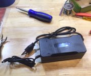
This is definitely a low-cost unit but does include a fan (despite the product description). My charger happen to have a small solder ball rattling around inside that I had to pull out before operating.
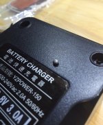
With the solder ball out, I ran a full charge on the battery pack and saw the charger continued up to 59.17V, which works out to 4.23V per cell. 4.2V is the maximum cell voltage recommended by the manufacturer, and running the cells that high will severely limit the potential life. I was pretty uncomfortable being above 4.2V but didn't want to spring $100 for an adjustable charger.
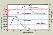
I figured this was a CC/CV (constant current / constant voltage) charger that turned off at a set voltage (in this case, 59.17V, instead of the specified 58.8V ). The circuit inside is pretty straight forward but I was only interested in the DC-output side of the large isolation transformer, which is shown on the right. Note I've disconnected the fan which plugs into the white 2-pin connector.
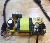
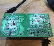
The bottom of the board has surface mount components including one i.c. each that control the circuits before and after the transformer.
I was hoping the small I.C. on the right would be some type of switching controller circuit, meaning I could look up the part number and then figure out how the output voltage was controlled. I should have expected a simpler, lower-cost design, because Instead that 8-pin chip is an LM358G, meaning a dual op-amp. I assumed each channel was set up as comparators (comparing the output voltage to a fixed value, and turning the output circuit on and off)
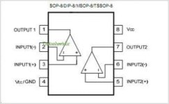
As I hoped, the outputs of this op amp each drive two cascaded transistors, where channel 1 activates the optical isolator to turn-on / turn-off the AC side of the circuit, which is how the charger is turned off at a set voltage. Channel 2 turns on the fan when the charge is operating. I focused on the inputs to channel 1 to figure out how the output voltage was being scaled and fed back into the comparator circuit. I only found one feedback trace from the charger output back to the comparator circuit, with three inline resistors that scaled the 59.17 output voltage down to 2.493V at the comparator.
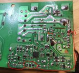
The resistors are 0K, 100K, and 4.99K, meaning a series combination of approx. 105K Ohms. I am targeting about 4.1V per cell (57.4V output). By using the ratio of the original output voltage over the current resistance, I calculated a new resistance to achieve a new output voltage,which worked out to 101.9Kohms. I have some 4.7K Ohm resistors handy, and putting one in parallel with the existing 4.99K resistor, will yield a total network of about 102.5kOhms. That's close enough for a low-tolerance circuit like this.
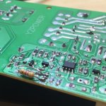
Afterwards I added insulating tape to protect the newly added component and buttoned the whole thing back together. The finished mod yielded 57.8V, which should greatly extend the life of the pack.
I ordered a BBSHD kit last month with a Luna 52V battery, and for $30 added the lowest cost, 3Amp charger, shown here: http://lunacycle.com/batteries/chargers/standard-3amp-52v-dolphin-shark-bottle-battery-charger/

This is definitely a low-cost unit but does include a fan (despite the product description). My charger happen to have a small solder ball rattling around inside that I had to pull out before operating.

With the solder ball out, I ran a full charge on the battery pack and saw the charger continued up to 59.17V, which works out to 4.23V per cell. 4.2V is the maximum cell voltage recommended by the manufacturer, and running the cells that high will severely limit the potential life. I was pretty uncomfortable being above 4.2V but didn't want to spring $100 for an adjustable charger.
I figured this was a CC/CV (constant current / constant voltage) charger that turned off at a set voltage (in this case, 59.17V, instead of the specified 58.8V ). The circuit inside is pretty straight forward but I was only interested in the DC-output side of the large isolation transformer, which is shown on the right. Note I've disconnected the fan which plugs into the white 2-pin connector.

The bottom of the board has surface mount components including one i.c. each that control the circuits before and after the transformer.

I was hoping the small I.C. on the right would be some type of switching controller circuit, meaning I could look up the part number and then figure out how the output voltage was controlled. I should have expected a simpler, lower-cost design, because Instead that 8-pin chip is an LM358G, meaning a dual op-amp. I assumed each channel was set up as comparators (comparing the output voltage to a fixed value, and turning the output circuit on and off)

As I hoped, the outputs of this op amp each drive two cascaded transistors, where channel 1 activates the optical isolator to turn-on / turn-off the AC side of the circuit, which is how the charger is turned off at a set voltage. Channel 2 turns on the fan when the charge is operating. I focused on the inputs to channel 1 to figure out how the output voltage was being scaled and fed back into the comparator circuit. I only found one feedback trace from the charger output back to the comparator circuit, with three inline resistors that scaled the 59.17 output voltage down to 2.493V at the comparator.

The resistors are 0K, 100K, and 4.99K, meaning a series combination of approx. 105K Ohms. I am targeting about 4.1V per cell (57.4V output). By using the ratio of the original output voltage over the current resistance, I calculated a new resistance to achieve a new output voltage,which worked out to 101.9Kohms. I have some 4.7K Ohm resistors handy, and putting one in parallel with the existing 4.99K resistor, will yield a total network of about 102.5kOhms. That's close enough for a low-tolerance circuit like this.

Afterwards I added insulating tape to protect the newly added component and buttoned the whole thing back together. The finished mod yielded 57.8V, which should greatly extend the life of the pack.


