Motor cutting out with too much throttle

Snacks

1 W
Joined
Feb 2, 2022
Messages
54
Hi

I'm upgrading my ebike with a new kt controller. I set it up and now unless i twist the throttle very slowly there's this beeping and then the motor seems to cut out. The display stays on and only one time did it throw a throttle fault. Otherwise there's been no indication of error on the screen. I'm not sure if the issue or beeping is the controller or the battery. It only happens under load. If I prop the wheel up and use the throttle I can twist it all the way without any issue.

The controller is rated for 22A continuous 45amp max .I got a 48v 20ah LiFePo4 battery with a 50A continous 100A max BMS to go with it.

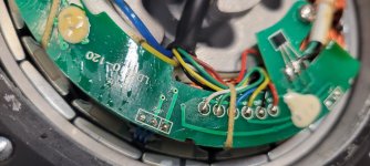
The connections didn't match .So I soldered the new controller in. I've checked and double checked the power connections to the battery and plugs . I even opened up the motor to make sure I set up the settings in the controller correctly.

The only other thing that may be off is that the motor had two extra wires, a white and brown. I think white is speed because when I opened up the motor there was a "SP" written next to where it was connected or i could be completely wrong in that assumption. I couldnt find where the brown went to inside the motor and the controller didn't have any extra wires for me to connect these to.

Any help is greatly appreciated !!
 

Attachments

  • 20220202_183503.jpg
    20220202_183503.jpg
    1.7 MB · Views: 709
Comrade said:
If you are into electronics and have experience with an Arduino or something similar that can bit bang 9600bps serial connections, temperature from the sensor can be injected into the data stream from the controller to the display. People have done it on this forum. I'm in the process of doing it.

Thanks for the suggestion. I actually came across this as well this morning. That and the open source firmware for the sine wave kt controllers that I can add temp monitoring with. Talking to the seller right now to see if I can exchange my controller for a sine wave version. I have one that is "dual mode" and as my motor has hall sensors i dont have a need for dual mode.
 
I just noticed the seller changed the ebay listing to say that this controller is for direct drive only. Trying to research this , i couldnt find anything to say why a controller could only be used with direct drive and not a geared hub motor. Does anyone have an ideas on that?

Luckily, I have a screenshot of the original listing to use to get a refund from eBay , if needed.
 
Snacks said:
I have one that is "dual mode" and as my motor has hall sensors i dont have a need for dual mode.

In the interest of troubleshooting, have you tried operation with the motor’s hall sensors disconnected? Forcing the controller into “sensor less” mode. Is the operation effected for better or worse?
 
unfortunately , connecting a second battery to help with sag didnt change anything with the issue .


TommyCat said:
Snacks said:
I have one that is "dual mode" and as my motor has hall sensors i dont have a need for dual mode.

In the interest of troubleshooting, have you tried operation with the motor’s hall sensors disconnected? Forcing the controller into “sensor less” mode. Is the operation effected for better or worse?

oh i have not tried that yet. ill give that a shot here in a little bit and see what happens.
 
Snacks said:
I just noticed the seller changed the ebay listing to say that this controller is for direct drive only. Trying to research this , i couldnt find anything to say why a controller could only be used with direct drive and not a geared hub motor. Does anyone have an ideas on that?

This is probably why it's missing the white wire. It would not need it since the motor would always be turning and your speedo will always work using the motor position halls.

Snacks said:
Nothing changed running it sensorless , unfortunately .

Like nothing nothing? Maybe it's running sensorless even with the sensors connected. Maybe they are not even sending any signal for whatever reason?
 
Comrade said:
Snacks said:
I just noticed the seller changed the ebay listing to say that this controller is for direct drive only. Trying to research this , i couldnt find anything to say why a controller could only be used with direct drive and not a geared hub motor. Does anyone have an ideas on that?

This is probably why it's missing the white wire. It would not need it since the motor would always be turning and your speedo will always work using the motor position halls.

Snacks said:
Nothing changed running it sensorless , unfortunately .

Like nothing nothing? Maybe it's running sensorless even with the sensors connected. Maybe they are not even sending any signal for whatever reason?

Oh ok yea that makes sense. I honestly couldn’t find any other reason for it to be direct drive only.

Oh no sorry I meant nothing changed in respect to the problem. It did run different sensorless compared to when I was using the sensors. It had a really rough start and didn’t run as smooth when the wheel started spinning.
 
I’m now certain the issue is with the controller. I cut open the battery to check the BMS and it was 50A continuous. Then I used my buddies new controller that came in yesterday, it’s a brainpower 38A controller, and everything worked perfectly. Unfortunately, he wouldn’t let me keep it :D

Testing the controller, it seems to cut out at about 25A even though it’s rated for up to 45A. Looking at some options to fix this it seems I can try to add solder to the shunts. Any other ideas that could possibly fix this? It seems weird to me that it would have this issue being an 18 mosfet controller. So I’m thinking maybe they’re really low quality fets that can’t handle the amperage?

Although, I can fix it I think I should have received a working product from the start, I’m not sure how hard it’s going to be to get CSC to replace this or work with me to get it fixed when they’re out in china.
 
What are the motor's current (amperage or wattage)draws under different conditions? I.G. Unloaded low and hi, Loaded low and hi...

Would you mind listing your display's "P" & "C" parameter settings?
 
TommyCat said:
What are the motor's current (amperage or wattage)draws under different conditions? I.G. Unloaded low and hi, Loaded low and hi...

Would you mind listing your display's "P" & "C" parameter settings?

P1- 100
P2- 1
P3- 1
P4- 0
P5- 15

C1- 6
C2- 0
C3- 8
C4- 0
C5- 10
C6- 3
C7- 0
C8- 0
C9- 0
C10- N
C11- 0
C12- 4
C13- 0
C14- 2

One thing to note- if c5 is set to 3 where it’s limiting the current to 50% of max then everything works. It’s slow and doesn’t have much torque but at least it works. Anything above 3 and the issue is present

I do apologize if this is a dumb question but how would I go about checking the current the motor draws? I assume a meter needs to be put inline with the power connection but I’m not sure what to do with the three phase wires
 
Just looking for battery amperage draw from the controller/motor during operation... I thought you had such a capability from this...


Snacks said:
Testing the controller, it seems to cut out at about 25A even though it’s rated for up to 45A.

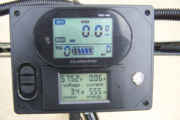
I find that this display installed inline with the battery power tells me what I want to know...

https://www.amazon.com/gp/product/B013PKYILS/ref=ppx_yo_dt_b_search_asin_title?ie=UTF8&psc=1


3siWKdu.jpg
 
TommyCat said:
Just looking for battery amperage draw from the controller/motor during operation... I thought you had such a capability from this...


Snacks said:
Testing the controller, it seems to cut out at about 25A even though it’s rated for up to 45A.

I find that this display installed inline with the battery power tells me what I want to know...

https://www.amazon.com/gp/product/B013PKYILS/ref=ppx_yo_dt_b_search_asin_title?ie=UTF8&psc=1


3siWKdu.jpg

Oh I’m sorry I misunderstood you. I can test the current draw from the battery to the controller but I didn’t know if you wanted to see how much the motor is drawing from the controller to compare .

With C5 parameter at 10
No load- 1.1 amps
Load - around 20A until it cuts out

I might have done something differently the other day to get it to cut out at 25A. Today multiple tests had it cutting out around 20A . On the display it does show wattage draw and it’s cutting out around 1000W which is consistent with the amperage measured.

What’s confusing is if I turn the throttle very very slowly I can get it up to 41A under load. It just takes a very long time to accelerate that way . With my friends 38A controller I was able to go full throttle no problem. It did almost wheelie every time but I was ok with that :D

But that’s looks pretty nifty. I just ordered one, thanks for the tip!
 
Making my way through your parameter settings.
Stuck on P1. :shock:
As it’s magnets times gear ratio, and looking at motors similar to yours I come up with a higher number…
Do you have the exact specs on your motor, and how you came up with 100?

The no load amperage is at max throttle?
 
TommyCat said:
Making my way through your parameter settings.
Stuck on P1. :shock:
As it’s magnets times gear ratio, and looking at motors similar to yours I come up with a higher number…
Do you have the exact specs on your motor, and how you came up with 100?

The no load amperage is at max throttle?

oh really? maybe thats incorrect then. i watched this video from bolton on the parameter settings - https://www.youtube.com/watch?v=B0F6x8V0NZQ
and then opened up the motor , the gear ratio is 5:1 . 90 teeth on the casing and 18 the axle (with the 36t planetary gears in between)
and 20 magnets around the outside of the motor. so i assumed it was 20x 5

yes, the no load amperage was with max throttle
 
TommyCat said:
I’d say you have it right on the money. Nothing beats actual eyes on counting teeth and magnets!
Roger on the amp draw… Thank you.

Ok good to know! I appreciate all the time and help
 
Opened up the controller yesterday to look for any shorts or bad connections. Such a tedious process. I followed the traces on the pcb to make sure there wasn’t extra solder or that anything was cut. Nothing really stood out to me. All the connections looked good .

I’m not sure what else I can test or try with this thing to either fix or find a reason for failure. I’m about ready to just chalk it up to a “bad controller” but I hate doing that without knowing why it’s gone bad.

On the other side of things Helin from CSC has yet to respond about a return or replacement. Hoping that’s just due to spring festival and I might hear something closer to the 23rd
 
Also ordered a bafang 062 1000w to lace into the wheel and a sabvoton 60v 45A sine wave controller . Hopefully I have better luck there. I think I’m going to take my batteries apart and put together a 60v LiFePo4 battery but I think this all needs another thread outside of troubleshooting.
 
Snacks said:
I just noticed the seller changed the ebay listing to say that this controller is for direct drive only. Trying to research this , i couldnt find anything to say why a controller could only be used with direct drive and not a geared hub motor. Does anyone have an ideas on that?

Luckily, I have a screenshot of the original listing to use to get a refund from eBay , if needed.

My guess is that the change could be since, based on your other posts, the controller can run sensorless. A geared motor is turning at a much higher RPM, so the controller running in sensorless mode, may not be able to function at those higher speeds. DD motors are turning in the hundreds of RPMs, not thousands.
 
Snacks said:
I’m not sure what else I can test or try with this thing to either fix or find a reason for failure.

From the correct operation at half current. And someone mentioned a sagging battery idea that you checked out.
Perhaps a bad battery wiring connection to the controller that's dropping battery voltage...? Perhaps checking for resistance from connector to PCB terminals. Looking closely for cold solder joints, pins, and connector contact points.
Can you change your displays read-out to show voltage so you can monitor for possible voltage drop?
 
TommyCat said:
Snacks said:
I’m not sure what else I can test or try with this thing to either fix or find a reason for failure.

From the correct operation at half current. And someone mentioned a sagging battery idea that you checked out.
Perhaps a bad battery wiring connection to the controller that's dropping battery voltage...? Perhaps checking for resistance from connector to PCB terminals. Looking closely for cold solder joints, pins, and connector contact points.
Can you change your displays read-out to show voltage so you can monitor for possible voltage drop?

I thought it could be the connections from the battery to controller as well but I’ve cut and soldered that a couple times now to make sure. I thought maybe it could be the way I’m soldering it, but the connection was solid and worked great with my buddies 38A controller when I tried that. All the same, I’ll go back and check resistance and check for the rest that you suggested as well.

The display shows voltage already. I can’t remember which C parameter it is but there is one that determines how the controller displays the voltage. Right now that’s set to 15 as per the recommendation from the Bolton ebike video for 48v batteries. It supposed to be a smart calculation of the battery voltage and not actual battery voltage. Not sure what the difference is just did it based on their suggestion. Currently ,the fully charged voltage for the battery shows around 56V then If I try the bike out it drops to around 52V in about 30 seconds . Mind you, this is using the throttle from zero and accelerating at a snails pace so as not to trigger the problem. Essentially going down a straight flat street until the bike hits 22mph. I’ve tried it a few times with the same results.

I think I’ll have to change that C parameter to where it shows actual voltage of the battery and try this again. Thinking about it, having the smart voltage calculation set up in the controller might be preventing me from seeing any sag or voltage drop on the display.
 
If anyone was curious about the resolution, the seller of the controller concluded it was a bad controller and sent me a new one. Although I paid the difference on a 60V version for the replacement. They still sent me another 48v controller :( but it works as intended! No issues whatsoever anymore .
 
Back
Top