Motor cutting out with too much throttle

Snacks

1 W
Joined
Feb 2, 2022
Messages
54
Hi

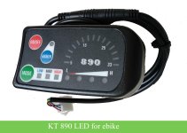
I'm upgrading my ebike with a new kt controller. I set it up and now unless i twist the throttle very slowly there's this beeping and then the motor seems to cut out. The display stays on and only one time did it throw a throttle fault. Otherwise there's been no indication of error on the screen. I'm not sure if the issue or beeping is the controller or the battery. It only happens under load. If I prop the wheel up and use the throttle I can twist it all the way without any issue.

The controller is rated for 22A continuous 45amp max .I got a 48v 20ah LiFePo4 battery with a 50A continous 100A max BMS to go with it.

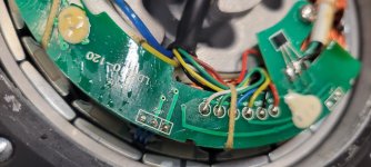
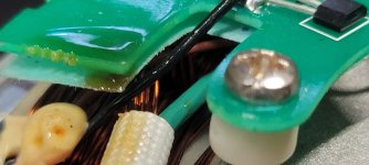
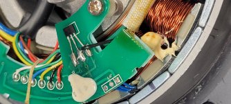
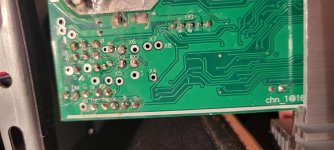
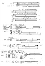
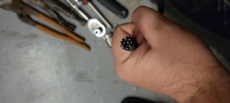
The connections didn't match .So I soldered the new controller in. I've checked and double checked the power connections to the battery and plugs . I even opened up the motor to make sure I set up the settings in the controller correctly.

The only other thing that may be off is that the motor had two extra wires, a white and brown. I think white is speed because when I opened up the motor there was a "SP" written next to where it was connected or i could be completely wrong in that assumption. I couldnt find where the brown went to inside the motor and the controller didn't have any extra wires for me to connect these to.

Any help is greatly appreciated !!
 

Attachments

  • 20220202_183503.jpg
    20220202_183503.jpg
    1.7 MB · Views: 709
Continuing research on the issue and I found that the SP wire normally refers to a throttle cable. So my issue might be steming from the fact the white wire is not connected. Since I dont have that on my controller, does anyone know if it would be ok to connect that to the signal cable coming from the throttle itself?

Otherwise I'm thinking about opening up the controller and hoping there's a pad to solder a throttle cable myself
 
Snacks said:
does anyone know if it would be ok to connect that to the signal cable coming from the throttle itself?
No it wouldn't, no throttle wires go directly to the motor. Is the brown wire loose? Not sure how you can't tell where is goes if you had the motor open and could just look.
 
Good to know. I definitely wont do it then, thanks

There was some type of plastic tie-downs holding the board down and I didn't want to cut them.

Took another crack at it and was just able to move them out of the way . I can now see where the brown wire goes. You can see it in the picture . I'm not sure if I can remove that glue or whatever the white stuff is to see what exactly it's connected to.
 

Attachments

  • 20220203_135627.jpg
    20220203_135627.jpg
    1.1 MB · Views: 660
  • 20220203_135458.jpg
    20220203_135458.jpg
    1.2 MB · Views: 660
On the controller side of things , does anyone know which pad might be where I can connect the SP wire from the motor. It's a kt controller
 

Attachments

  • 20220203_165643.jpg
    20220203_165643.jpg
    1.8 MB · Views: 651
Maybe brown is a temp sensor? There is a weird black wire soldered to the ground pin of your speed hall sensor. Measure what brown wire has on it when the motor is plugged in and powered on.

The KT controller had no thin white wire coming out of it and going to the same plug as motor position hall sensors?
 
I'll test the brown wire as soon as I get home from work.

No, there was no white wire coming out of the kt controller going to the hall sensor plug. I attached the wiring diagram that came with it. It even shows the spot where the wire should be on the plug as empty.

I wonder if anyone with a kt controller that does have the white wire can open it up and let me know what pad it's soldered to. I've been looking for a picture for the most of the day without any luck.
 

Attachments

  • Screenshot_20220203-190431_eBay.jpg
    Screenshot_20220203-190431_eBay.jpg
    401.4 KB · Views: 641
I can look at my controller later today. It came with a white wire in the #2 slot.

What kind of display are you running with the new KT controller? Maybe this KT controller is some OEM for a cheap bike that was supposed to have only a simple display that doesn't display speed? Hopefully the firmware still has the functionality to read and display speed, and it's just the physical wire that is missing.
 

Attachments

  • e-bike-kt-890-led-24v-36v-48v.jpg
    e-bike-kt-890-led-24v-36v-48v.jpg
    327.9 KB · Views: 625
Can you provide a picture of the connectors from the cable coming out of the motor. You may be fortunate enough to have at temp sensor installed in the motor, but it would be unusual to see more that 6 (small) wires coming out of the hub. SP could mean speed, but most of the time one of the hall sensor signals can be used to determine speed if the motor is direct drive.
 
Comrade said:
I can look at my controller later today. It came with a white wire in the #2 slot.

What kind of display are you running with the new KT controller? Maybe this KT controller is some OEM for a cheap bike that was supposed to have only a simple display that doesn't display speed? Hopefully the firmware still has the functionality to read and display speed, and it's just the physical wire that is missing.


I had my buddy test the brown cable as he is a bit more confident using a multimeter with the motor plugged in and powered on. He confirmed brown was a temp sensor. I had to re solder the black wire as it might have been coming into contact with the 3rd prong of that hall sensor.

I finally did find some pictures of a kt controller but between the 3 pictures I found, two used the X5 pad and one used the x4. However, I did read elsewhere that x4 is usually used as an analog input to the controller. My controller has both x5 and X5. I'm hoping you also have X5 used when you open yours up. And if thats the case, I might be able to use x4 for the temp sensor, if it's actually another input.

I'm using an kt-LCD8h with the controller. I just purchased the controller from CSC through ebay but I was told it was the latest and greatest. It's the one that comes with Bluetooth so you can make use of a phone app with it instead of a display too. The model number listed on top is KT48ZWSRKTB-SJT02LB. It does display speed when I set p2 to 0 and it does seem fairly accurate when comparing it to the speed from the strava app.

Btw, Thanks for the help! Fingers crossed this missing white wire is the fix.
 
E-HP said:
Can you provide a picture of the connectors from the cable coming out of the motor. You may be fortunate enough to have at temp sensor installed in the motor, but it would be unusual to see more that 6 (small) wires coming out of the hub. SP could mean speed, but most of the time one of the hall sensor signals can be used to determine speed if the motor is direct drive.

Yea I've been told this motor is a bit weird on that it has a 10 pin coming our of the motor. The usual 8 plus white and brown

The motor is a geared hub motor. Based on some info from the manufacturer and a bit of sleuthing, I know it purchased from Found motor Co in China but couldn't get much more info from them about it. The case and internals, minus the brown wire, seem like an exact match to a bafang 500w 060 motor when comparing them.
 

Attachments

  • 20220204_064612.jpg
    20220204_064612.jpg
    1.4 MB · Views: 613
Debating on getting a 1000w bafang 062 to replace this motor but I'm wondering if I'll have the same trouble with this white wire on that motor . That's assuming not having this wire hooked up is the root cause of my throttle issue
 
Hi Snacks,

Snacks said:
That's assuming not having this wire hooked up is the root cause of my throttle issue

As your new controller is not expecting a speed sensor input from your WHITE wire with the input wire not provided.
And you mention that you have speedometer readings.
I find it unlikely that ether the WHITE or BROWN unknown wires from the motor (RPM hall sensor input and temperature sensor thermistor input) would have an effect on your problem. Although I do commend you for wanting to find out. And having a motor temperature sensor would be a plus.

But to me the problem, no power or operation with minimal load and making noises. Would seem to be more of a bad motor hall sensor to phase winding configuration problem. Especially as you've just changed over to a new controller with no "learning" wire or automatic configuration capabilities. (any on the app?)
I notice that the wiring between the two, (motor and controller) changes the position of the hall sensor's outputs to the controller's input. Still in same sequence, but different.

First thing I would do is get a current measuring device between the battery and controller. And see if it's using more current than normal to verify a bad combination choice or possible motor damage. Then check the motor's hall sensors operation... see
Testing BLDC motor's Phase Wiring - Hall Sensors and Wiring.


And if all is well, proceed to finding the correct combination.


HRaeRi4.jpg


Just my take...


Respectfully submitted,
T.C.
 
TommyCat said:
Hi Snacks,

Snacks said:
That's assuming not having this wire hooked up is the root cause of my throttle issue

As your new controller is not expecting a speed sensor input from your WHITE wire with the input wire not provided.
And you mention that you have speedometer readings.
I find it unlikely that ether the WHITE or BROWN unknown wires from the motor (RPM hall sensor input and temperature sensor thermistor input) would have an effect on your problem. Although I do commend you for wanting to find out. And having a motor temperature sensor would be a plus.

But to me the problem, no power or operation with minimal load and making noises. Would seem to be more of a bad motor hall sensor to phase winding configuration problem. Especially as you've just changed over to a new controller with no "learning" wire or automatic configuration capabilities. (any on the app?)
I notice that the wiring between the two, (motor and controller) changes the position of the hall sensor's outputs to the controller's input. Still in same sequence, but different.

First thing I would do is get a current measuring device between the battery and controller. And see if it's using more current than normal to verify a bad combination choice or possible motor damage. Then check the motor's hall sensors operation... see
Testing BLDC motor's Phase Wiring - Hall Sensors and Wiring.


And if all is well, proceed to finding the correct combination.


HRaeRi4.jpg


Just my take...


Respectfully submitted,
T.C.

I appreciate all the info! Thank you

Unfortunately no learning ability on the app.

Originally I thought it was the same. I tried the six combinations of connections between yellow ,blue and green phase wires . The only combination that actually turned the wheel ,other than matching all the colors (which im using currently), was

controller motor
Yellow -> green
Blue -> yellow
Green -> blue

But when I used that combination and turned the throttle I could hear the motor spin within the housing but the wheel wouldn't spin for the first few seconds. Then it felt like something would catch inside the motor and then the wheel would start spinning. I checked to see if maybe I stripped the planetary gears inside the motor but they still look great. When the motor does catch and the bikes starts moving everything works as normal and it's just as smooth as the other combination of wires. It really only has an issue from a zero start .

I'll have to check the current and test hall sensors here still. It's a new bike and motor (two 15mile rides) so I'm hoping all of that is in working order.
 
Snacks said:
I finally did find some pictures of a kt controller but between the 3 pictures I found, two used the X5 pad and one used the x4. However, I did read elsewhere that x4 is usually used as an analog input to the controller. My controller has both x5 and X5. I'm hoping you also have X5 used when you open yours up. And if thats the case, I might be able to use x4 for the temp sensor, if it's actually another input.

My white wire is going to the X5 pad. My PCB is a little different though, I have 7 holes in a row where the a, b, c from hall sensors go.

I highly doubt you can just connect something to x4 and for it to work. Firmware on the controller would need to know to read from that pin, and how to read it.
 
Comrade said:
Snacks said:
I finally did find some pictures of a kt controller but between the 3 pictures I found, two used the X5 pad and one used the x4. However, I did read elsewhere that x4 is usually used as an analog input to the controller. My controller has both x5 and X5. I'm hoping you also have X5 used when you open yours up. And if thats the case, I might be able to use x4 for the temp sensor, if it's actually another input.

My white wire is going to the X5 pad. My PCB is a little different though, I have 7 holes in a row where the a, b, c from hall sensors go.

I highly doubt you can just connect something to x4 and for it to work. Firmware on the controller would need to know to read from that pin, and how to read it.

Ok that's good news! Thanks for checking! I do have 7 in a row where the last hole is labeled x5. And then there is a pad above it labeled X5. it seems as though x5 might be the one since in the row but X5 has the same label I've seen on other kt controllers

Yea you're right I'm going to skip trying to attach the temp sensor.


edit - i was wrong, i only have 6 in a row on my controller but the x5 that was the 6th in the row was the correct one.
 
Snacks said:
controller motor
Yellow -> green
Blue -> yellow
Green -> blue

But when I used that combination and turned the throttle I could hear the motor spin within the housing but the wheel wouldn't spin for the first few seconds. Then it felt like something would catch inside the motor and then the wheel would start spinning.

Sounds like the clutch needs servicing. And since it's a geared motor, it's pretty sure the white wire was the speedo signal for the stock controller. Must have been a decent controller if it had temp monitoring/protection.
 
Thankfully, clutch is fine. That was the wrong combination of phase wires.

x5 turned out to be the correct pad for the white wire. Speedo works off the white wire now with the correct p2 setting, 1 for this motor.

The controller actually has a temp monitor but I'll spend some time later trying to figure out the correct pad for that.

None of this fixed the problem though. I went back through steps TommyCat suggested. Everything checked out and going back through all the combinations to see if there was one better than the current one but none were.

At this point I'm thinking maybe the battery seller might have been incorrect on the BMS. I think next step has to be cutting open the battery pack to check it myself
 
Snacks said:
The controller actually has a temp monitor but I'll spend some time later trying to figure out the correct pad for that.

Was it advertised to have temp monitoring ability?

I had someone from Kunteng reply to an email from me asking about that specifically, and they said that if the controller has firmware to monitor temps, it would have the letter "C" in the model number.

KT48ZWSRKTB-SJT02LB does not.
 
Oh yea that's my mistake. I was reading the features of the display and mistook that for the controller features. The display has the option to show motor temp but you're right the controller was not advertised with that option.
 
If you are into electronics and have experience with an Arduino or something similar that can bit bang 9600bps serial connections, temperature from the sensor can be injected into the data stream from the controller to the display. People have done it on this forum. I'm in the process of doing it.
 
tomjasz said:
This is exactly what happens to me with battery sag.

Battery is charged up to full and showing over 53v on the display. I have a second battery that I can hook up that should help with sag . I give a try and see if it changes anything
 
Back
Top