You are using an out of date browser. It may not display this or other websites correctly.
You should upgrade or use an alternative browser.
You should upgrade or use an alternative browser.
Motorcycle Class Cargo Bike: Power, Distance, Stealth, Grins
- Thread starter ryan
- Start date
ryan
10 kW
Also, any advice on how to cleanly cover the sides of my running boards?
ryan
10 kW
Regarding the side covering for the running boards. I have a couple ideas. Can you help me flush them out?
I expect to adhere the running boards using just longer bolts that attach directly to the running board frame (roughly 100mm). That's 10mm x 2 for both boards, 5-10mm for screwing into frame, and 69mm to cover the gap. Further I expect to cover each of the bolts between the boards with a plastic (or metal, I suppose) spacer tube.
Here are a few options to cover the sides:
1) Fabric - Wrap the entire outside with some sort of fabric (leather, plastic, heavy vinyl, etc.)
2) Semi-flexible - Some sort of semi-rigid solution that could be bent into shape, (aluminum?). Perhaps even milling a tiny channel in each board to "seat" the side covering.
3) Wood - get some thin wood board, and attempt the same as #2 above. Rigid and heavy and a leans looking amateur, but I think could work.
Some questions:
1) What do you recommend to cover the sides?
So far I'm leaning towards #2 above, wrapping in flexible metal, seated in a channel. But...
2) How could I cut an appropriately thick aluminum sheet 7cm tall (maybe 7.5cm if I cut a channel) by (roughly) 1.68m wide? Is this something I could get a big box hardware store to do for me on the cheap?
3) What thickness of aluminum do you recommend? (or alternatively, another metal and thickness) I expect the bolts themselves to take the most of the weight (if a passenger stands up on the board, for example). So the sides don't need to provide any (or much) structural support.
4) How would you recommend cutting a channel into the plastic running boards to "seat" the side cover? Dremel by hand?
john7700
100 W
Go with some stiff but still bendable plastic sheeting for the covers. Cut them to shape using a skill saw. I would think 1/4 inch sheeting should do and probably available at Homy Dupont. Cut the receiving groves in to the running boards with a router or a dremmel with a router detachment. Glue in place with construction adhesive on top board if necessary. Also for the weight bearing bolts attaching the upper to the lower, run the bolts through an appropriate lengths of 1/4 or 1/2 inch metal pipe/tubing (between the boards) so the weight is on the tubes and not on the bolts.
Just my $0.02
Just my $0.02
ryan
10 kW
Thanks John. 1/4" seems pretty thick for (what I think will be) mostly cosmetic. Is there a reason to go that thick? And why plastic over metal? I was thinking with metal I could go thinner, but I have little to no experience with either.
I'll have to ask around to see if anyone I know has a router I can borrow to set the grooves up.
The metal pipe for weight bearing is exactly right. Thanks.
I'll have to ask around to see if anyone I know has a router I can borrow to set the grooves up.
The metal pipe for weight bearing is exactly right. Thanks.
ryan
10 kW
Also, if I'm going to route out the grooves, I might as well route out some "seats" for the battery packs as well. Maybe I can get back some of the height if I knock off 5mm from each side of the running board sandwich. Any concerns about that? That still leaves 5mm of thickness where the batteries lie, and 10mm everywhere else.
I may also "seat" the metal tubes a bit as well and add an extra one or two pipes for good measure to add strength (particularly on the inner side).
I may also "seat" the metal tubes a bit as well and add an extra one or two pipes for good measure to add strength (particularly on the inner side).
john7700
100 W
I was thinking plastic for two reasons, because it is easier to work with and be cut, shaped and molded with tools you probably have on hand. Secondly because it will bend and not dent and become miss-shapen. Where you are mounting this is a likely spot to get kicked leaned against etc. I was kind of spitballing the thickness but go to thin and you could crack it to easily.
I went for a ride after my last post and was thinking about this (my best thinking time is in the saddle) and I remembered a material that I used several years ago for ceiling tiles in a wet room in brewery that could work well here. It is the same material that you some times see on commercial bathroom or kitchen walls. It comes in a 4x8 sheet and has a textured surface. It is made to be tough and mar resistant and I think it would be plenty stiff at the width your talking about. As I recall however, it was kind of pricy at like $32 a sheet but readily available . Home depo might sell you a half sheet. But, go looking at the supply stores and see what kind of material you might be able to find.
Grooving out battery space sounds like a fine idea. You could probably go another inch on each side and still be safe. Actually, hold on for a second. Why use the over heavy and pricy second set for the tops. Why not just neatly cut out some half inch marine plywood to match the shape of the bottom pieces? Plenty strong, much thinner leaving more room for batteries, shaves quite a bit of weight and would be much less expensive.
I'll definitely be fallowing this thread as I am thinking of something similar for my next build. Lots of pictures
please
ryan
10 kW
Kitchen tiles = genius. I'll make a trip to the hardware store soon to handle in person. That could be the ticket. The comment about dents in metal makes perfect sense too. Plus, I wasn't sure how I'd cut it anyway. If Home Depot wouldn't do it for me, I'm afraid it'd look pretty amateur in my hands.
Re: wood top board -- I'll think about it. Sounds more trouble than it's worth right now (at least for my skill set), but once I figure out how to groove the existing boards, I may see it differently.
Feel free to throw all your ideas my way and I'll see if they work, then you can do it the right way with your build.
john7700
100 W
Again, they aren't really tiles. The material comes in a 4x8 sheet. We were cutting them down to use as 2'x4' ceiling tiles. At the supply store mention commercial bath room walls and they should know what you mean. They may be able to suggest something else perhaps something more flexible. No matter what material you end up with, you are going to have to make some custom cuts that you will only be able to measure correctly when things are mocked up. You are either going to have to figure a way to cut it or find a carpenter who can help you out. You might even want to pay some one who has the right tools to make some cuts and groves for you. But, everything here could be done with a Drummell and if you are feeling frisky you could tackle it yourself.
As far as the running boards, I took a look at them on the web site and realized I was looking at the size incorrectly. For $65 you are probably better off going with the pre-made plastic ones.
I'm thinking of the top board, sides and metal tubes as a one piece cap that goes over the bottom board and batteries as one piece, slots in to a groove and bolts down. Also, your going to want to seal the holes in the running boards to seal the battery area from elements, gravel, puddles etc.
Out for now,
John
ryan
10 kW
Re: Tiles
Exactly right. I didn't know of a better way to say it. I guess I'm thinking of black, tough linoleum flooring, sold in sheets. But a trip to a big box hardware store will sort it out right quick.
Re: Professional vs. Dremel DIY
If I wanted it done right, what sort of tools are needed for the job? I can ask around if I know the right question.
I've been dreaming up some concoction involving a drill, a dremel bit, and a thick wooden dowel appropriately cut to serve as a bit guide around the board. But I'd like to know what the pros would do.
Re: Running boards
I may be able to get them for $40-$45 as well. Trying to work that out.
Re: Sealing Holes
That's another problem. I anticipated sealing the bottom holes (on the bottom running board), but I might need the top holes since they help latch down the panniers (to be used at least occasionally). Ideally I could have plugs for these holes to pop in and out, but even then I may need slight holes punched in the sidewalls to allow the strap to go through. I'll work this out when I get my mock up done. I have paper boxes built exactly to scale (well printouts now, until I tape them up into boxes). Another possible solution is to wrap the electronics up before putting the top on. Since I plan on opening it up and balance charging once a month I could see how dirty the inside gets after wrapping in a simple plastic bag to start with. I don't typically ride in the rain (by choice), so it may not be entirely essential. But the bottoms should be sealed for sure. (any particular recommendation there? Otherwise I might just glue gun them closed!)
ryan
10 kW
Other good news, the M5 bolt I need for the running boards is available in 100mm length.
ryan
10 kW
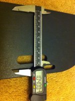
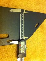
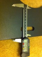
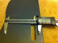
Well, you did ask for tons of photos...
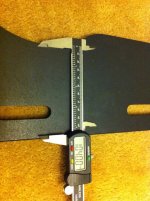
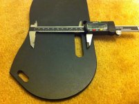
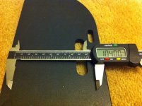
Here's my battery layout test. What do you think? I've never used LiPo. How much padding is necessary between or on the edges of packs for wires?
Is this just too tight to make work?
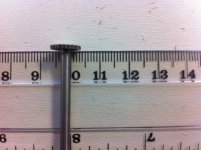
The caliper is marked at 104mm (exactly twice the 52mm width of the 165x69x52 6S1P 8Ah LiPo packs). It's tight for sure.
Other important measurements:
* The bolt hole to the outside is 8mm
* Bolt hole itself is 9mm
* The narrowest point (from the neck of the middle curve to the outside) is 112mm
* The rest of the width is tapers between 130 and 134mm
I put up another thread asking about the precision of HobbyKing LiPo specs. Hopefully they over-estimate, but I'm not counting on it.
This leaves very little room for a groove to seat the sidewall. I may have to run it on the edge near the narrow neck in order to make it fit.
 View attachment 3
 View attachment 1
Here's my battery layout test. What do you think? I've never used LiPo. How much padding is necessary between or on the edges of packs for wires?
Is this just too tight to make work?
The caliper is marked at 104mm (exactly twice the 52mm width of the 165x69x52 6S1P 8Ah LiPo packs). It's tight for sure.
Other important measurements:
* The bolt hole to the outside is 8mm
* Bolt hole itself is 9mm
* The narrowest point (from the neck of the middle curve to the outside) is 112mm
* The rest of the width is tapers between 130 and 134mm
I put up another thread asking about the precision of HobbyKing LiPo specs. Hopefully they over-estimate, but I'm not counting on it.
This leaves very little room for a groove to seat the sidewall. I may have to run it on the edge near the narrow neck in order to make it fit.


 View attachment 3
 View attachment 1
999zip999
100 TW
Use the washers with rubber on one side for the bolts. And make a mockup up your side covers out of red rosin paper for constrution. But you need to weight for the batts to see reel size for that tight fit you have. Can use the running boards on top and the marine plywood on bottom so as not to be to worry about looks, when cutting it yourself. Plus it will give a factory look. I like it when I have guianie pig to fallow.
ryan
10 kW
Sidewall update:
I couldn't find any kitchen flooring that matched John's description at Home Depot. I did find a bunch of tiles and standard linoleum flooring, but nothing in 8x4 sheets. However, I didn't ask around either, so I might need a second trip.
However, I did find that standard rubber wall base you see everywhere and picked up a few yards for a couple bucks.
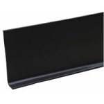
This wall base is 2mm thick and might just be sturdy enough to make work. I can easily cut it to size and will be plenty flexible to make the corners. My only concern at this point is it's vertical flexibility. It might be fine with the bolts as reinforcements, or might be too loose and collapse on itself. We'll see.
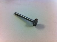
For the grooves, I also picked up a dremel bit to test out. The bit is 1mm thick and goes 3.2mm deep (1/8in). I'll test it out on some wood to see how it holds the wall base.
If it works, I expect I'd be able to put the groove 2-3mm from the outside. Then, make the groove about 1.8mm wide (to squeeze the sidewall base a tiny bit). That would leave at 3mm between the base groove and the bolt holes. This shaves 4-5mm from each side, meaning that even at the narrowest point (112mm) I'd have 104mm left to play with (exactly twice the 52mm width of the LiPo packs). The good news is that I could fudge a little on the inside of that narrow point and run the side wall closer to the edge (even right on the edge), if necessary.
If that's correct, the wall base will be cut to 75mm tall (69mm for LiPo + 3mm seated in each running board).
I couldn't find any kitchen flooring that matched John's description at Home Depot. I did find a bunch of tiles and standard linoleum flooring, but nothing in 8x4 sheets. However, I didn't ask around either, so I might need a second trip.
However, I did find that standard rubber wall base you see everywhere and picked up a few yards for a couple bucks.

This wall base is 2mm thick and might just be sturdy enough to make work. I can easily cut it to size and will be plenty flexible to make the corners. My only concern at this point is it's vertical flexibility. It might be fine with the bolts as reinforcements, or might be too loose and collapse on itself. We'll see.
For the grooves, I also picked up a dremel bit to test out. The bit is 1mm thick and goes 3.2mm deep (1/8in). I'll test it out on some wood to see how it holds the wall base.
If it works, I expect I'd be able to put the groove 2-3mm from the outside. Then, make the groove about 1.8mm wide (to squeeze the sidewall base a tiny bit). That would leave at 3mm between the base groove and the bolt holes. This shaves 4-5mm from each side, meaning that even at the narrowest point (112mm) I'd have 104mm left to play with (exactly twice the 52mm width of the LiPo packs). The good news is that I could fudge a little on the inside of that narrow point and run the side wall closer to the edge (even right on the edge), if necessary.
If that's correct, the wall base will be cut to 75mm tall (69mm for LiPo + 3mm seated in each running board).


ryan
10 kW
So looks like another hassle with the flexible sidewall option is going to be fitting the top of the sandwich on correctly. Putting the sidewall in the base is straight forward enough, but the top will be another story. I may have to carve out a larger groove at the top to accommodate a larger margin of error. It won't seat tightly, but it will be easier to put the top back on after balance charging.
Another challenge is to allow the battery enclosure (affectionately, "running board sandwich") to be removed all at once, particularly when fixing a flat. Ideally when I intend to remove the whole sandwich I shouldn't need to take the sandwich apart. Instead just lay it to the side as I access the wheel bolts. I'm thinking that two extra bolts running through the sandwich could keep everything tight if so desired.
Another challenge is to allow the battery enclosure (affectionately, "running board sandwich") to be removed all at once, particularly when fixing a flat. Ideally when I intend to remove the whole sandwich I shouldn't need to take the sandwich apart. Instead just lay it to the side as I access the wheel bolts. I'm thinking that two extra bolts running through the sandwich could keep everything tight if so desired.
ryan
10 kW
john7700
100 W
Hmmmmm.... that does look awfully tight at the pinch point for the axle. I run Lifepo and haven't used lipo yet so I'm not sure exactly how much room you need for wires, expansion etc. but it looks like if the bottom board was 1/2- 3/4 of an inch wider, the space issue would go away. That would bring me back to thinking about a custom lower board. Since you have the pre-fabbed board to use as a pattern, you would just need to make the outside edge an appropriate amount wider. Then you could attach the lip of the rubber kick plate to the outside of the top board to make it wide enough to align with the widened bottom board and slots.
On the rubber kick plate, I think it should work. Something a little more rigid would seem preferable however. Hard to think about these kind of things some times when you can't see it/hold it in your hand. It does not need to be structural as the bolts/tubing should be bearing all the weight. I would think you will want the slots as deep as you can get away with to prevent it from popping out. Also, I think the best bet would be to attach the rubber to the top running board like a cap or lid that then it drops down in to the slots in the bottom board.
On the slots, I'm not to sure about that bit you picked up. It might work, but it seems to me that it is going to try to pull itself all over the place making it real hard to make precise groves. I was thinking of a plunge bit that is shaped more like a conventional drill bit with cutting edges on the twist and is run with the dremel. Let me take a quick lap around the web and see if I can find the ones I've used before: Ah,here it is

Also, these dremel router bits come in various widths:

Mounting the dremel in one of these attachments would make it much more controllable (~$13):

Or better yet, if you want to spend a little more $ this would be ideal (~$26):

Have you thought about the bolt sleeves yet? Perhaps some proper diameter copper pipe? Or even some chrome pipe from the bath department.
That's what I've got for now.
Keeps us posted.
J
On the rubber kick plate, I think it should work. Something a little more rigid would seem preferable however. Hard to think about these kind of things some times when you can't see it/hold it in your hand. It does not need to be structural as the bolts/tubing should be bearing all the weight. I would think you will want the slots as deep as you can get away with to prevent it from popping out. Also, I think the best bet would be to attach the rubber to the top running board like a cap or lid that then it drops down in to the slots in the bottom board.
On the slots, I'm not to sure about that bit you picked up. It might work, but it seems to me that it is going to try to pull itself all over the place making it real hard to make precise groves. I was thinking of a plunge bit that is shaped more like a conventional drill bit with cutting edges on the twist and is run with the dremel. Let me take a quick lap around the web and see if I can find the ones I've used before: Ah,here it is

Also, these dremel router bits come in various widths:

Mounting the dremel in one of these attachments would make it much more controllable (~$13):

Or better yet, if you want to spend a little more $ this would be ideal (~$26):

Have you thought about the bolt sleeves yet? Perhaps some proper diameter copper pipe? Or even some chrome pipe from the bath department.
That's what I've got for now.
Keeps us posted.
J
ryan
10 kW
Is it realistic to expect a rotary tool to cut a running board from marine plywood? Or just the grooves?
If I wanted to DIY it, what rotary tool would be up for the challenge?
Sent using Endless-Sphere Mobile app
If I wanted to DIY it, what rotary tool would be up for the challenge?
Sent using Endless-Sphere Mobile app
john7700
100 W
I can't really think of a way to do it with a dremel. Probably the best and safest
tool for the job would be a jig saw.
If you are going to make your own and return one set of the $65 pre-made ones
then a half sheet of good plywood for ~12.00 (you don't really need marine grade
if you paint it and aren't leaving it out side ) and one of these from Home Depo
for $29.95 and you are ahead of the game and you now own the tool.
*Edit: After thinking about it, The first bit I pictured might cut the plywood especially
if it was locked in to the second router housing but I wold still use a jig saw if I could.
Also, the jig saw with a mettle blade would cut the bolt sleeves smoothly.

Pure
10 kW
In regards to your side panels on the battery runners. I would use the rubber material you have already found but also use small angle aluminum stock as a support frame. 3-4 pieces of stock installed along both sides of the runners could be used/screwed in such a way to hold the whole battery "sandwich" together. This would aid in keeping it all in one piece for removal.
ryan
10 kW
I found some aluminum tubing at the hardware store today. On its own I'm not sure it's thick enough, but I'm thinking about nesting a few. So far I have a 1/4 and a 9/32 nested and it seems pretty strong. I'll consider another layer after some stress testing. $4 got me enough for everything.
Also, regarding wiring... I have a ton of HobbyKing 4mm gold bullet connectors. But is that enough for my plans? Or do I need 5mm?
Also, regarding wiring... I have a ton of HobbyKing 4mm gold bullet connectors. But is that enough for my plans? Or do I need 5mm?
ryan
10 kW
I'm making another part order for my running board compartment and came across some electrical-grade fiberglass 1/8" x 3" x 72" that caught my eye for the sidewalls. Any reason I should choose this over the vinyl wall base?
I've never worked with fiberglass at all. How easy would it be to mold it to my runningboard shape? Special tools required, or some heat?
-- further update --
Batteries will be ordered next week. And hopefully our 5404's will get here within a few weeks.
I'm also re-considering building out the runningboards from scratch using some steel. Price is right, and if I can figure out how to cut it effectively without much expense, it could cut my runningboard thickness down a bunch, while giving a little extra room for batteries. Still working out the details.
ryan
10 kW
Update... I'm back in town and the weather here is wonderful. I took out my sons on my new Yuba Mundo v4 today, unpowered. The difference between the v3 and v4 is night and day. I barely felt the kids at all (on level ground!). I can't wait to get the 5404 installed.
I also ordered a bunch of miscellaneous parts for the running boards from McMaster-Carr... thick aluminum spacers, 100mm and 120mm M5 screws, nuts and some nord-lock washers for my x5304 and x5404. I should get them in this week and finally put together the running boards. Or at least a solid attempt. I'm waiting to see how this looks before ordering the batteries.
I also ordered a bunch of miscellaneous parts for the running boards from McMaster-Carr... thick aluminum spacers, 100mm and 120mm M5 screws, nuts and some nord-lock washers for my x5304 and x5404. I should get them in this week and finally put together the running boards. Or at least a solid attempt. I'm waiting to see how this looks before ordering the batteries.
ryan
10 kW
The "analog" part of the build is coming together... disc brakes, rotors, regular brake cable + extra long tandem brake cable (for rear), caliper adapter for rear disc and more are in hand or will be by the weekend.
I'll also have all of the running board pieces ready to take a crack at what it all may look like. I just got my Nord-Lock washers, aluminum spacers, extra long M5 screws and all sorts of little goodies from McMaster. Time to see what these boards will look like and how they'll come together.
And I placed an international HK order for some extra 5.5mm gold bullets, 8mm bullets, and a ton of silicon wire. And a cell log for good measure (hey, I had room left for shipping).
I'm waiting on purchasing the batteries still, but they're in the US warehouse so they can be here within a week at any time. Hopefully the real life mockup will confirm everything will work out and I can order them.
Now I'm starting to diagram the battery pack, LVC, wiring layout. Wish me luck.
ryan
10 kW
I'm thinking of using AJ's harness to minimize wiring requirements and provide (hopefully) fool-proof connections. Can I get someone who knows about this stuff to verify I'm on the right track?
Both of these packs represent one side of the bike. Just with series (biking) and parallel (charging) configurations. (That is, if I understand how all this works!)
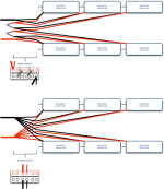
The end result should look something like this:
I haven't figured out how to wire the balancing wires yet (currently marked by thin blue lines on each pack. Here's what Method's said, but I'm still reading it over and over until I actually understand it. I'm in over my head. I'm going to be using his LVC/HVC boards.
I'll throw a diagram together for Method's plan for your feedback once it clicks in my brain.
Both of these packs represent one side of the bike. Just with series (biking) and parallel (charging) configurations. (That is, if I understand how all this works!)

The end result should look something like this:
I haven't figured out how to wire the balancing wires yet (currently marked by thin blue lines on each pack. Here's what Method's said, but I'm still reading it over and over until I actually understand it. I'm in over my head. I'm going to be using his LVC/HVC boards.
methods said:ryan said:Back to the LVC/HVC boards... let's say the right side is the "main pack" where I have 3 of your boards and 6 packs of Zippy LiPo 6S in 18S2P configuration. The left side then just has 6 packs of LiPo.
So the left side will also be configured in 18S2P. We will gang up the 2P's so that we end up with 3 JST 6S plugs - high, mid, low. We would then have to run those three cell level jumpers over to the main pack to ensure all 4 cells are parallel at the cell level. You would also have to run the main power and main ground over there.
ryan said:Are you saying that I could add 3 "Method's custom paralleling boards" (MCPB, for ease) to the left side and then have 3 extension cables going from the MCPBs to the LVC/HVC boards on the right side? And then I can bulk charge via the right side's LVC/HVC boards?
The bulk charging goes into your main power and ground lines right? So that can happen on either side. Your balancing solution that taps into the LVC/HVC boards can go into either the main side or the aux side as well - since it is all in parallel it is all the same. The idea is just to parallel them up however we need to.
The LVC signal to the throttle would come only from the main side. If you choose to implement the HVC charge control that would also come from the main side. Basically - from an electrical point of view the pack is all just paralleled - even though one bank of your pack is physically separated - electrically (schematically) it is all together in one spot.
So if the distance is 2 feet you will need:
2 foot main ground jumper ( I suggest 10AWG+)
2 foot main power jumper
2 foot JST-XH-7 for cells 1-6
2 foot JST-XH-7 for cells 7-12
2 foot JST-XH-7 for cells 13-18
That is assuming the left side does local paralleling (which I will make for you free of charge. Simple small board that has 4 x JST-XH-7 board connectors on it.
The trick is building those 2 foot JST jumpers and deciding how to terminate the ends. I would terminate them with sockets (electrical sockets that plug into board mount pins - so male connector housing). I would offer to sell you one but the engineer who I employ costs $30/hour and it would probably be something you could do for cheap. JST-XH-7 jumpers are cheap. If I were you I would buy a bag full, cut them down the middle, extend them, sleeve them with a non-abrasion sleeving, mark them well, and go to town. Just dont mix up High, Mid, and Low unless you like buying / fixing stuff.
-methods
I'll throw a diagram together for Method's plan for your feedback once it clicks in my brain.
Similar threads
- Replies
- 42
- Views
- 58,597


