Motorcycle Class Cargo Bike: Power, Distance, Stealth, Grins

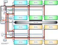
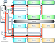
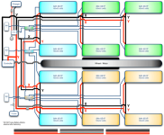
Methods is suggesting an alternative (simpler, reliable, cheaper) wiring scheme. Essentially 3 packs of 6S4P wired in series for 18S4P. I've reached out to him to confirm this is what he's suggesting, but here's my mockup of his notes:
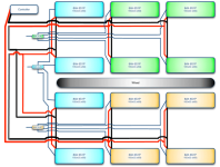
battery-wiring-4P.png


Things I'm unclear about...

1) When I bulk charge, what do I connect to? Just charging leads off the main leads? Or at the LVC/HVC/Parallel boards?
2) Methods has a new HVC Breaker circuit that's supposed to go between your charger and the LVC/HVC/Parallel boards. But how do I connect the LVC/HVC/Parallel boards in series? Is there an extra slot for that?
3) When I balance charge, can I leave my pack assembled and just use the connections at the LVC/HVC/Parallel boards? (this would be way easier given my enclosure design)
4) How do I balance charge this pack?
5) Also, seeing as how I need to extend the balance wires, how do you recommend doing that?

HK sells 20cm JST extensions for cheap, but I'm going to need at least 5 balance wires that reach closer to 30-35cm (4 for each of the 6S1P packs at the back and one to go across the wheel to the other side). Should I buy a couple 10-packs of these and solder two together when necessary? Or is there another suggested method?

I really appreciate all the feedback and advice so far. This whole build is over my head, so I'm especially grateful for the all the wisdom shared here.
 
Hi Ryan. Looks fine. This is great if you plan to leave both sets of batteries on all the time, and it saves a lot of trouble. As I recall initially you had a requirement to run on one bank of 2P and make the second removable, but that does cause a lot of complications and that requirement lead to the earlier design with separate LVC/HVC boardsets.

Those 6S extensions will plug into each other as they are male-female, so they can be daisy chained as needed.

The LVC/HVC boards have two jacks for daisy chaining the signals, so as you had drawn before there is a cable between each of them, a 5S cable, so you might need extensions for that also. Then the one charging cutoff board takes a 5S cable from one end to control it. It sits between the bulk charger and the main output leads. Then a BMSBattery type bulk charger feeds into that.
 
Update, based on Alan's input. Is this closer?

battery-wiring-4P.png

Bulk charging is making sense to me. Get a big charger (say this 900w unit from BMSBattery), connect it to the HVC and we're good to go.

Balance charging is still a bit of a mystery. Methods is recommending using Battery Medics. But I'm unclear on how to use them without disassembling the enclosure. Where do I plug the Battery Medics in? Do I need to unplug anything first? Does the battery medic just go in between each LVC board in the chain and then connect to the charger as usual?
 
Booster Pack question...

In the event that I need more Amp hours (let's say 8Ah more), it seems to me that I'd have to build a separate 18S1P pack, haul it along unconnected, and switch the connectors to the new pack when I run out of the 18S4P main pack. Does that sound right?

If so, that would mean a booster pack shopping list looks something like this:
1) 6S1P Zippy 8Ah LiPo (x3)
2) 1 HVC/LVC/Parallel board from Methods


( I know what you're thinking... "32Ah isn't enough!?" But I have in mind some epic rides on this bike that might require a whole lot more Ah. It all depends on real world Ah/mile though, so I'm not building the booster just yet. )
 
I got an update from Methods on the diagram and charging. Here's the summary.

Diagram is looking good.

Bulk charging... connect a big bulk charger directly to the HVC Breaker (like the diagram).

Balance charging... connect Battery Medics to each LVC board (as shown in diagram). Set charge/discharge appropriately. Charge. Disconnect Battery Medics.

battery-wiring-4P.png

Looks like I'm good to go! PM sent to Methods for the necessary parts. -- which should complete my required shopping list for phase one!

Special thanks to Alan, Fractal, and Methods for setting me straight.
 
ryan said:
In the event that I need more Amp hours (let's say 8Ah more), it seems to me that I'd have to build a separate 18S1P pack, haul it along unconnected, and switch the connectors to the new pack when I run out of the 18S4P main pack. Does that sound right?
Why would you haul it along unconnected? It would be easier on your whole pack including that booster if you left them all connected in parallel all the time. Easier to charge it, too. ;)
 
The booster wouldn't be used all the time. Just for especially long rides. 32Ah is really good for nearly every ride I'll take on. But there are a handful of long routes I'd like to hit up occasionally.

The reason I say I'd need to keep it unconnected is because my main 18S4P pack will be very difficult to reconfigure once set up. The main pack will be set up in 3 groups of 6S4P wired in series for 18S4P.

So let's say I made an extra 6S4P pack. If I wired it in series I'd be at 24S4P. But my goal for the booster would be additional Ah, not volts. That's why I say each 8Ah booster will be 18S1P (6S1P x 3) plus a LVC board. Then I can simply connect the leads to the controller and I've got more gas in the tank. Make sense? Or am I misunderstanding something critical?
 
It'll work that way, but you'll be putting 3x the load on that pack than you did on your main pack, so the cells will wear up to 3x faster than your main pack.

Plus you end up spending twice as much money on the Methods' boards, since you already will have 3 of them on your main pack, and now you will have to buy 3 more to use on your spare pack.

FWIW, each board could have up to 8 packs plugged into it--7 if you use one of the plugs for a balancing connector for external balancers...seems a waste not to use the existing boards if you can. ;)
 
Ah I see what you're saying. And yes, I was misunderstanding how many LVC's I'd need for a booster. I suppose I could just go commando and just watch the Ah draw and bring a cell log to check in. Otherwise I think I'll focus on getting this rig up and running as is first before I start getting too ahead of myself. Thanks for the input.
 
What do you recommend to cover the wires that run between the running boards?

I'll have one group of wires that run from one deck to the other, and a second set that run from one deck to the controller.

I have plenty of heat shrink, but is that what I should do? The goal is clean, sturdy, stealth.

Deck to Deck:
8awg (x2)
10awg (x2)
JST-XH-6 (x3)

Deck to Controller:
8awg (x2)
 
Fuse: what's the max current the charger can handle? 18A. So you can use a slow-blow glass-tube type fuse at something above that rating. It can be one of the AC type fuses, because they are rated to break a circuit at least 125-250VAC; your voltage will be half that DC. Better would be a fuse rated for DC at that voltage, but it's possible the regular one will work. One that would be better is the sand-filled type, because if an arc occurs it will melt the sand and block it's own path with glass. :)


Covering the wires: Will there be any chance of something rubbing thru them? Ground strike? If so, you could use a metal shield around them, like the stainless braided water hoses I got from a recycled home-building materials place. Otherwise, heatshrink could work; there is less expensive plastic tubing you could use, though. You can probalbly find something for next to no cost at a thrift store that would work.

You could also run them within the framework, if you have tubes that run from one side to the other. (I haven't looked back at the rest of your design yet).
 
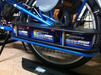
HK USA delivery! 32 pounds of LiPo arrived today. All packs measured 22.9v and had no signs of deformation. Cell levels were close to 3.85v on nearly every one of the 72 cells. There were 2 at 3.82v and 1 at 3.72v. Once my Battery Medics arrive I'll balance them, charge, discharge, charge to see how level they get.

My Methods shipment gets here on Saturday, so I might have the weekend to make some decent progress.

It's going to be a tight fit to build this to my spec.

zippy delivery 1.jpg
View attachment 4
zippy delivery 3.jpg
View attachment 2
View attachment 1
zippy delivery.jpg
 
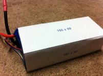
I had hopes of getting a lot more done today. Unfortunately I underestimated the effort required for paralleling all the packs. Hats off to icecube57 for his soldering and paralleling skills. That's a lot of work.
 
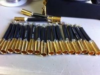
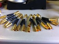
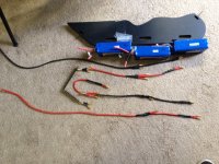
My assembly line:

photo 1.JPGphoto 2.JPGphoto 3.JPG

Now I need to duplicate this in red with male bullets (so it's impossible to mis-wire polarity). 4 Y's and 3 X's (where Y = 2 to 1, and X = 3 to 1).

Key learning... my butane soldering iron rocks and made this so much faster than my electric.

Incidentally, what do other people use to insulate the bullets from their helping hands? I used cardboard scraps but I figured others might have less of a gerry rigged approach.
 
You might want to check out IC57's video on those bullet connectors. He does them on an electric range burner. Way cool.
otherDoc
 
Cool, I haven't seen that video. My butane iron does pretty well though. I can't complain.

Speaking of icecube57, here's a video I'll save here for reference:

[youtube]Va8mRBzglIU[/youtube]

Update:
Here's the referenced video...

[youtube]5GH6x28tDII[/youtube]

I love the silicone housing on the pliers idea. I'll be adding silicon covers for my helping hands today.
 
Updated diagram. Some wiring efficiencies for better cable management. Added a new fuse between pack and controller, HVC. And approximated the wire connector lengths necessary to join all the packs (at the bottom).

battery-wiring-4P.png

X = 3 to 1 connection
Y = 2 to 1 connection
 
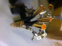
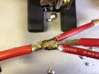
So it turns out I was a handful of 8mm bullets short from completing my connector plan. Instead of waiting a few weeks for HK or even a few days from some other US source, I abandoned it midway in favor of the copper wire wrap method. My quick experiment yielded a thinner, strong connection that should be able to handle the same current. Here are some pics...

View attachment 3
photo 2.JPG
View attachment 1

10awg into 8awg.

And here's my approximate layout. It doesn't look like much, but it's coming together, at least in my head.

photo 5.JPG

Just a handful more wire harnesses to go.

IceCube57 was the inspiration for the switch. He recommends using copper crimp sleeves, but I had some solder tinned copper wire on hand so I made it work. Either way, the result is strong. These connections aren't going anywhere. But it does take time. I recommend letting IceCube57 do this for you if you can afford to do so. As you can see I'm doing a lot of trial and error learning here so I wasn't exactly sure what would work.

I hope to get the remaining harnesses done tonight and start on the JST extensions.
 
If it was facebook i would give it a like not because of the promotion but u do good work.
 
Back
Top