mxus 60A KT controller pics and some upgrade shots

macsboost

1 mW
Joined
Mar 3, 2015
Messages
14
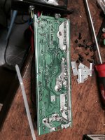
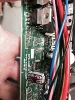
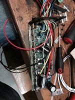
Here are some before pics of the guts of a 72V "60" amp 12 mosfet controller, sold by MXUS for the 3000W motors. It is rated for 30A continuous, 60A peak. This is the highest power controller they offer.

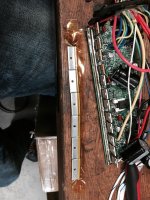
The high current traces had some wire tacked on at several spots. It wasn't fully saturated with solder. The phase and feed wires are 12AWG teflon or tefzel. I will add some wires for the power, maybe for the phase wires later.

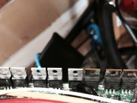
The fets on one of the phases were visibly different but the same part #. I wonder if they are genuine.

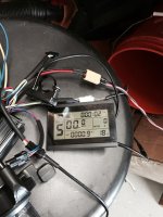
The controller came with the LCD3 V2 lcd display.
Some variables are programmable with the LCD such as current, regen force, etc.
http://www.szktdz.com/upload/file/20150319/20150319095301_95014.pdf

It has an allegro hall effect current sensor and a shunt for cycle analyst (not sure if it uses the shunt internally for current control, or the allegro?) Why are there two? My guess is the shunt is just for the analyst.

I have yet to try it as I am still waiting on a frame. However, it does run reasonably well when the motor is clamped in my vice. :)

IMG_5951 (Medium).JPG
IMG_5952 (Medium).JPG
 
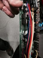
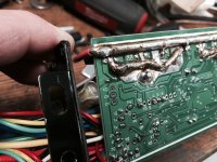
Behold the beefed up traces..
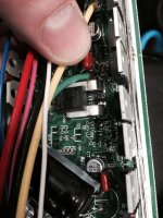
You can see the hall effect current sensor. I believe It could be replaced with a 150A unit, then adjust the current parameters accordingly and this would allow 90A max.

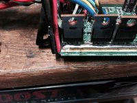
I added a second 12awg power feed/ground. The positive side I ran to the other side of the mosfets.. This should reduce the voltage drop on that side of the controller more.


For reassembly, I used kapton to hold the mosfet clamps together.. This worked well.

IMG_5955 (Medium).JPG
IMG_5956 (Medium).JPG
IMG_5957 (Medium).JPG
IMG_5958 (Medium).JPG
View attachment 4
IMG_5964 (Medium).JPG
Here you can see the additional power feed, attached to the other end of the + side of the rail. This should lower Vdrop to the mosfets on this side.
For the ground, you still have to go through the shunt, so I attached the extra ground to the proper side of the shunt.

My antique 140W weller gun worked perfectly for adding the extra solder and wires to the board, but was about as big a job as it is capable of soldering. I wouldn't attempt this with less wattage.

IMG_5965 (Medium).JPG
IMG_5966 (Medium).JPG
IMG_5967 (Medium).JPG
 
This is the lower-voltage version of the one I tested here:
http://endless-sphere.com/forums/viewtopic.php?f=31&t=66559
There will be a new version coming out soon, that is reported to include variable regen and support of low-inductance motors like the MXUS 3000W 3T motor.
 
This is the same 72v, 59-90v version.

You can adjust the regen level with the lcd. So you are saying a new one is coming that will work with a 0-5v proportional brake signal?
 
macsboost said:
This is the same 72v, 59-90v version.

You can adjust the regen level with the lcd. So you are saying a new one is coming that will work with a 0-5v proportional brake signal?
That's what is sounds like. I'm in the queue to test once they are ready.
 
my motor arrived with the white wire, but didnt seem to have the temp sensor installed.
If I ohm it out I get an open circuit to ground or the hall power.

Anyone know if the controller needs an LM35 or a 10K ntc.

Also, my controller didnt have the temp input connected. Anyone know where it needs to go.
I was able to enable the temp display on the LCD.
 
macsboost said:
my motor arrived with the white wire, but didnt seem to have the temp sensor installed.
If I ohm it out I get an open circuit to ground or the hall power.

Anyone know if the controller needs an LM35 or a 10K ntc.

Also, my controller didnt have the temp input connected. Anyone know where it needs to go.
I was able to enable the temp display on the LCD.

The motor's temperature input (White wire & Shared Hall ground) would go to your CA V3 or an Ohmmeter/oven temp sensor. It doesn't connect to the controller.
 
Back
Top