new eZip motor

Status
Not open for further replies.
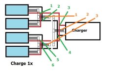
Your charge 2x diagram has two chargers. I don't get that. Also what are Anderson connectors?
 
latecurtis said:
Your charge 2x diagram has two chargers. I don't get that.
Alternative charging method.
3 separate charging methods diagrammed.
Charge 2x - for 2 chargers or 1/2 pack charged at a time

file.php

Charge 1x - for 1 charger for charging all cells at once (requires 3rd balance Y and additional power Y's)

file.php

Bulk Charging - for performing the simplist non-balance charge (VMA 's highly recommended with scheduled balance charges also!)

file.php

latecurtis said:
Also what are Anderson connectors?
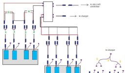
Thought I saw Anderson powerpoles Y connectors in one of your little pictures.
Must be bullet?
Better because they are universal, no male - female differentiation.
 
For balance charging all 4 6s packs from a single 6s charger you will need 6 power Y cables and 3 - 6s balance Y.
2 power and 1 balance always connected to charger.

file.php


4s LiPo packs will be a totally different subject! Not so simple!
 
I only see 4 bricks on charge 1x Why do I need 6 power cables.
 
Please just let me know if figure 1 attachment on my first post will work. I can find a switch and get the job done from there. I don't care if I have to switch balance plugs because I will do that at home. I wont need to balance charge on the road just top off the packs with the sky charger. Sunder . Dan. What's up. I would like to hear from you guys.

Thanks. Latecurtis out.
 
6 power Y, single wire, 3 red 3 black - indicated by green
3 balance cables - indicated by orange

file.php
 

Attachments

  • 44.4V_Cables.jpg
    44.4V_Cables.jpg
    24.5 KB · Views: 1,624
latecurtis said:
Please just let me know if figure 1 attachment on my first post will work. I can find a switch and get the job done from there. I don't care if I have to switch balance plugs because I will do that at home. I wont need to balance charge on the road just top off the packs with the sky charger. Sunder . Dan. What's up. I would like to hear from you guys.

Thanks. Latecurtis out.
No idea which "first post" you are referring to ... or why you would want to use a switch?

Any of your "figures" I looked at looked excessively complex and sadly non-specific ... couldn't figure what you were trying to do.

My methods are much simpler and circuits are valid.
 
Might have found "Figure 1".

Your diagram appears to use 6 double wire Y power connectors (Green).
With some unknown 2nd function for other side of Y, of 1-4. They must not be attached to charger wires at same time!
5 and 6 look to each be 2 single Y connections, so you are using 4 double power Y and 4 single power Y ... 8 power Y! ... ?

You use same 3 balance Y's but hard wire some connections. (Orange)

file.php
 

Attachments

  • LCfiguire_1.jpg
    LCfiguire_1.jpg
    43.6 KB · Views: 622
The 1, 2, 3, 4 in green I can hard wire everything from the plugs below them and eliminate the Y connectors all together. The other side of Y is simply all 4 bricks wired in parallel for 22.2 volts. It should be the same as charge 1x. in your diagram. That switch should be simple to find. The benefit of the switch is to eliminate any plugs or wires from shorting out on the metal box and wear and tear plugging and unplugging everything. The center position will be 0 volts to each possible circuit. That is for hooking everything up safely. The switch also prevents any mistake hooking up the wires for charging.
DrkAngel please be patient as I am still learning. If you can please look at figure 2, 3, and 4. As you said 4s packs are totally different. That is why I was hoping to find a switch that would enable me to use the parallel board Dan sent me. He sent it to use on the 6s bricks but there are only 4 of those and the board has the capacity to charge 6 bricks. That is why I want to save it for when I get 6 - 4s bricks for two more 44.4 packs. I hope that I can find the switch for the 6s packs offline at a store somewhere. In two days I get a little money and can get another metal box. The switch i can wire up as soon as I get it. I wont be plugging anything into the Lipos until I have everything in place as I illustrated in Figure 2. I just want to make sure I did not make any mistakes in my diagrams. It has been almost 20 years since I took circuits 2 at the community college. So if you can look them over I would appreciate it. Thanks Latecurtis. out
 
Figure 2,3,4 are under figure 1. Thanks.
 
I made a mistake on figure 4. Should be 6 terminals on the bottom. There is only 5. That will be a hard switch to find but got plenty of time to look for it as that 6 - 4s bricks are at least a couple of months away.
 
All your diagrams seem designed as 1p.
You are using as 2p!

You are trying to think way too complex.
Rig your packs as 2p 1st, then consider them as 1 pack for diagram and function purposes.

Use pos & neg power Y plus balance Y to turn 2 - 6s1p packs into a single 6s2p pack 1st and view it as such.


Similarly, pair up your 6x 4s1p as they will be used >>> 3x 4s2p.
Write your circuit diagram as 3 - 4s packs.

Do not hard wire your packs together!
Connectors are reliable and allow easier diagnosis, repair and replacement.
 
Your buddy Doug might be interested in my Haro Express Deluxe conversion.
I built a 700C 8 speed rear QR wheel with an eZip motor capability.
With my 44.4V pack and low amperage controller, motor and pedals are 30 mph continuous cruising capable!

See - Haro Express Deluxe Build
 
Simple 44.4V run diagram

44.4V6s2p.jpg

Simple 22.2V charge diagram

 
Lipo BOARD.jpg
 
Instructions for ABC Lipo board. Find a piece of 3/4 inch plywood.. Cut to fit metal box.

Step 1.Using scrapwood drill holes with different drill bits for a tight hole.each plug should fit snug and not slide back out the hole. Drill all holes in board with wood drill bit exact size for female plug to fit in tight. The diagram should be in front of you on screen or color printed paper during all steps.


Step 2. Clearly label each hole with red and black permenent marker.

step 3. starting with 6 inch connector batt1 Attach female plug and run each wire to clearly labeled hole. Put glue around each plug and insert from bottom into hole. Do not rush this step.

step 4. using same plugs hook each battery wire from parellel board to labeled hole. see green wires in diagram.

Allow at least 24 hours drying time before using. Dont connect 6 inch plugs into lipo packs until inspecting all connections for integrety.
 
Grimmers electronics wanted $30 for the switch. Radio shack is looking for one. Decided it was too much trouble so I invented this. A bit of work to build but will be well worth the effort.

The only thing I could use help with is the choice of plugs or connectors. Board should not be too large as controller and parallel board also need to fit in metal box also. The Skycharger and 300 watt power supply will be housed in smaller box seperatly for portable bulk charging. The 400 watt charger and 550 watt power supply will balance the cells when charging at home.

It should be finished in a few days. Thanks Latecurtis out.

This post and my little invention were completed Sun and Mon. I caught something really nasty. Virus or Flu. I need a doctor. Thought was going to have to go to ER last night. Been in bed most of the time. Probably going tomorrow. With both e bikes down I got to either walk or call an ambulance. Please let me know about plugs. Do you think Bullet plugs will work. They cant be too long to reach across board and will need to make or order the special 5 prong plugs for bulk charging. All I need help with now. I got $100 from my mother for Christmas. She could not get near me though as she has a medical condition and cant catch whatever I got. She is going to Florida for Christmas. Must be nice. Hopefully I will be up and running by Friday or Saturday. I will need to order the plugs and wires. I hope to get this finished before Christmas so I can take the bike in my brothers pick up truck to his house if the weather allows and race some Amish horse and carriages. They are all over where he lives. I bet they never saw an e bike before. LOL. Latecurtis out.
 
Oh before I forget DrkAngel. I will need hookup for battery gauge If you can after making sure I did not make a mistake. I checked it multiple times. I will need to know how to hook up the battery gauge. very important. Gauge is better than alarm if possible. I don't need an alarm going off distracting me. thanks. Latecurtis.
 
Also Sunder and Dan I miss you guys. Please post when you can. I know you are probably busy with Christmas and all that. Thanks
 
Damn LC ...
Sure you're not some politician ... are you?

Taking a simple project and making it as complex and expensive as possible!
 
DrkAngel said:
All your diagrams seem designed as 1p.
You are using as 2p!

You are trying to think way too complex.
Rig your packs as 2p 1st, then consider them as 1 pack for diagram and function purposes.

Use pos & neg power Y plus balance Y to turn 2 - 6s1p packs into a single 6s2p pack 1st and view it as such.


Similarly, pair up your 6x 4s1p as they will be used >>> 3x 4s2p.
Write your circuit diagram as 3 - 4s packs.

Do not hard wire your packs together!
Connectors are reliable and allow easier diagnosis, repair and replacement.

Less confusing?
Added dual connector with jumper wire to diagram and angled the Y wires

To switch from run to charge: KISS ©®
1. remove jumper connector
2. remove volt meter alarms
3. remove controller

.... 44.4V Battery .... 48V Controller ....
44.4V6s2pcontroller.jpg
4. plug in power 2Y and balance Y from charger
(always leave Ys connected to charger )

.... 2x 22.2V Batteries .... 22.2V Charger ....
44.4V6s2pcharger.jpg

As simple and idiot proof as possible!
Unless unable to tell red from black ...
Possible with directionalized bullet connectors to further idiot proof! ... if deemed necessary?
 
After gaining confidence in your cells ...
No self-discharge
Cells of fairly equal capacity
You might feel comfortable trying a bulk charger. (scheduled balance charges ... every 4th?)
Proper condition Lithium cells tend to discharge-charge to same beginning balanced voltage levels.
(Excepting cells with self-discharge or excessive charge or discharge rates)

Connections are super simple.

To switch from run to charge: KISS ©®
1. Disconnect controller
2. Connect charger

file.php


44.4V6s2pBulkCharge.jpg

Monitor voltages with installed meter-alarms but!
Confirm with volt meter!!!
(Accuracy of Volt meter-alarms vary from unit to unit - I recommend buying spares and from multiple suppliers)

I build battery packs of accurately balanced capacity between banks and typically bulk charge 100+ cycles before "re-tuning" banks to precisely equal again.

But! I do check and monitor bank voltages on a regular basis.
 
latecurtis said:
Also Sunder and Dan I miss you guys. Please post when you can. I know you are probably busy with Christmas and all that. Thanks

Sorry man. Not sure what to post these days. Trying to get those last couple deals over the line, working hard at tweaking designs for our clients who want to sign off before Christmas.

About 1/3rd of my income is what's called "at risk". I get 65% of my income pretty much just for doing my job. I get another 15% based off security solutions that I design that actually sell, and 20% based off the company hitting $6m of profit a year.

I've got about 14% out of my 15, but the company number is only about 90% of where it needs to be - but at 99%, I get zilch, at 100%, I'm laughing, so I'm pitching in and trying to get a couple extra thousand out of each account to get us over. A lot of money at risk for me - let's just say I would still have a fair bit of change left over after buying a stealth bomber...
 
DrkAngel please look at Lipo board post again. I know it seems complex but it is because it is much more versatile. I will be switching chargers often as bulk charging will be done with my portable Sky charger and balance charging at home with a parallel board and 400 watt mega charger Dan sent me. The Lipo board makes sense and is virtually mistake proof. All I need is plugs and would like to order those tomorrow. That's why I call it the A B C Lipo board. It looks complex but is as simple as A B C. Everything is clearly labeled and if you check out the attachments under it you can appreciate the safety features.
I would like a battery gauge instead of an alarm as an alarm is a distraction during e bike operation. So plugs and the hookup for the gauge and link for the gauge is all that's missing. Please take a second look at lipo board and the two attachments below it. If you can please post those attachments the way yours are. I only know how to post them as attachments. I hope that Dan will appreciate them as he sent me the parallel board and wanted me to use it. He also sent the lipos ,power supply and Mega charger. I want him to know that I am going to put all to good use soon and not let everything collect dust in a closet. I went to the doctor today and got flu medicine. I will be at the library tomorrow. Thanks Latecurtis out
 
Too complex for me!

Rig packs as 6s2p ... to start.
Half as complex to figure.
Don't see any way simpler than my diagrams ...

Volt meter alarm tells full voltage and voltage of each bank and alarm function is adjustable, goes off when any bank is near empty, when empty or when battery is killed.

I can't believe you wouldn't want a warning before or while you are damaging your battery?
Best alternative would be a BMS that cuts all power just before severe damage point. ... ?
 
Status
Not open for further replies.
Back
Top