Had a good chance to do some coding recently. I made a few changes:
1) Ported it so I can now run it on F405 (VESC) based hardware
2) Removed all the magic numbers from the main FOC loop
3) Fixed up the sensorless algorithm.
Previously, I was running mainly with hall sensors, though I rode occasionally with the sensorless algorithm I made using a method where I simulated a hall sensor from the back EMF.
The new sensorless algorithm is what I want to write about today, wondering if anyone has any pertinent comments.
My concept (second concept) is as follows:
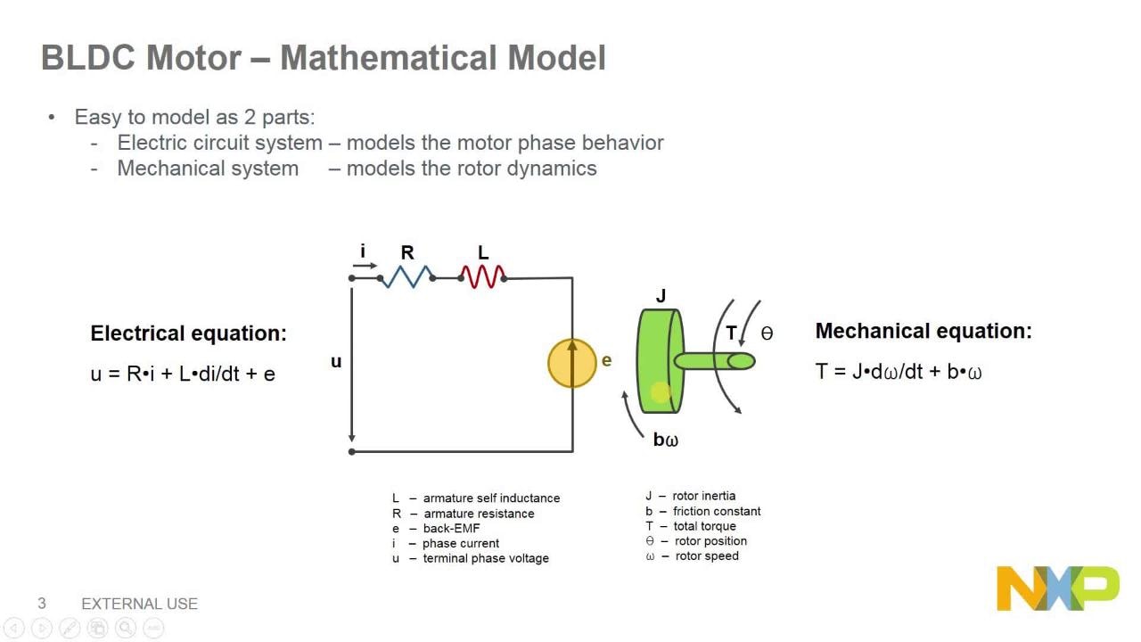
Vd and Vq are accurately controlled by the PID loops.
Va and Vb are, by necessity kept closely locked in with the rotor back EMF, and are the inverse park transform of the VdVq.
If you were to base the angle directly off the instantaneous back EMF, I think there would be serious stability problems because of rapid changes due to... noise, load... causing sudden back EMF jitter, pushing the angle wrong and then rapid runaway, BUT, if you low pass filter it, the noise and jitter goes away.
Low pass filtering is not desirable since it results in lag and error and slow response. However, we have a system that is strictly cyclical, and where it is therefore not necessary to have a decay time. Sinusoidal.
The integral of a sinusoid being a cosinusoid and so on, if you low pass with no decay, you introduce a phase shift of known magnitude - 90 degrees.
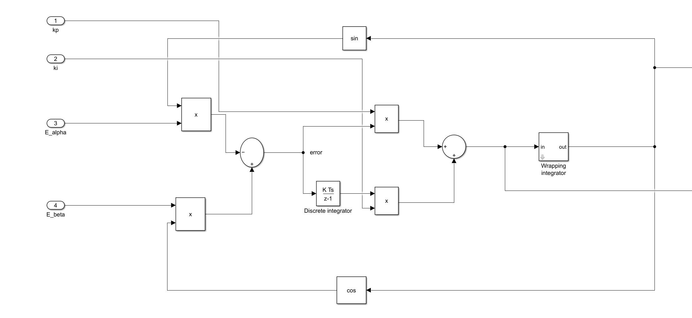
So, we perform the math:
Code:
void flux_observer() {
    // This function we are going to integrate Va-Ri and clamp it positively and
    // negatively the angle is then the arctangent of the integrals shifted 180
    // degrees
    BEMFa = BEMFa + foc_vars.Vab[0] - motor.Rphase * foc_vars.Iab[0] -
            motor.Lphase * (foc_vars.Iab[0] - Ia_last) * foc_vars.pwm_frequency;
    BEMFb = BEMFb + foc_vars.Vab[1] - motor.Rphase * foc_vars.Iab[1] -
            motor.Lphase * (foc_vars.Iab[1] - Ib_last) * foc_vars.pwm_frequency;
    Ia_last = foc_vars.Iab[0];
    Ib_last = foc_vars.Iab[1];


    if (BEMFa > motor.motor_flux) {  BEMFa = motor.motor_flux;    }
    if (BEMFa < -motor.motor_flux) { BEMFa = -motor.motor_flux;    }
    if (BEMFb > motor.motor_flux) {  BEMFb = motor.motor_flux;    }
    if (BEMFb < -motor.motor_flux) { BEMFb = -motor.motor_flux;    }

    angle = (uint16_t)(32768.0f + 10430.0f * fast_atan2(BEMFb, BEMFa)) - 32768;
  }
That is it, in it's entirety. The fast atan2 was borrowed from Oskar Weigl at Odrive, who had borrowed it from some public domain blog. Thanks to both, that simplified my life a load

.
The clamps on the flux integrals exist to deal with gradual drift in the integrals due to noise and current shunt offsets etc, and simply say "We know what the max integral is, it's a property of the motor, if it's larger than that, we have drifted due to noise so clamp it.".
The fast_atan2 returns an angle in radians, and I use uint16_t for my angles, so I correct for the phase shift and scale.
It works, with my 7pole pair 50-100kV motors it spins with low load down to about 10eHz and once above about 30eHz is thoroughly locked in and can handle aggressive grabbing the rotor, near instantly stopping it etc.
It runs both directions with no fussing, and can go through zero velocity easily, provided the acceleration is fairly rapid.
Observation of the phase angle the PWM/current makes with the hall sensors shows that it is basically phase correct, though clearly lagging by 1pwm cycle in the current implementation (for obvious reasons; last cycles data being used to predict this cycle's angle).
Downside (that I found so far) is that it refuses to run whatsoever with my tiny little 1200kV RC motor. I presume it simply can't see a back EMF at the speeds I can flick it up to by hand. I have not implemented any startup routine yet. (Edit: it works fine with the little motor, not sure what I messed up first time)
Have not tested with field weakening yet. This one might be problematic if field weakening actually does "weaken the field" and reduce the back EMF. (Edit, in the course of doing this, I have observed that field weakening does not actually weaken the field, and the observer works fine under moderate field weakening - tested up to 50A with an 8080 motor for nearly 2x base speed)
So why is this not a normal, standard method for sensorless control? It seems so simple and obvious that I only just tried it having previously thought it could never possibly work or everyone would be doing it. What's the catch? What's going to suddenly bite me?
Going to try loading it onto a bike and giving it some serious load, see if it stays stable when the motor is being driven close to it's saturation limits.
No video yet, unfortunately I actually implemented this on an F405 controller so I could simply discard the notion of saving clock cycles with a processor 2x as fast. I want to first share a video of it running on the original MESC hardware, not borrowed hardware. It will definitely back port to the F303, but I will need to do a bit of tidying up