New Kelly pseudo FOC controller series

I think I found what might be causing this problem. My OVER VOLT was not set high enough. I set it at 68V for 16S. I noticed that while recharging, I was in the set up and saw the controller showing the battery was at 66V but my voltmeter on the scooter was showing a bit over 64V. The voltage reading of the controller does not seem to be very accurate. I also noticed that the controller would need to be rebooted at the first intersection of my commute, right after I slowed down using the regen. So I'm thinking that the controller believed it saw spikes over the 68V I set it at. So tonight I set the OVER VOLT to 70V and tomorrow morning I will see if I am right.
 
this sounds like a good explanation. but still it's a bit weird. why would the controller shut down? shouldn't it just prohibit and regen if voltage is close to HVC and NOT enable regen at all?? at least this is imho the only thing that makes sense. why else should the controller have HVC? a raising voltage during operation can only be acchieved by regen, and if you connect an overcharge battery to the controller, what can happen? nothing. expect the voltage is higher than the rated voltage of the controller, and in this case the damage is already done (eg. blown caps etc ..)
 
izeman said:
fany said:
1,This controller was opened and modified too much.We can not be sure if the modifications will affect the performance too much.Because we don't know how is the modification on the PCB board, Mosfets etc. But I think it could affect the controller a little bit.

2,Please confirm if you get the special App from our customer. I only sent this special APP to one customer.
Then keep the max output Fre at 1000.Please adjust the max speed to 6000.

3,What is the rated RPM of the motor?And we may need to know the gear ratio and pole pairs of the motor.

4,How many RPMs is the much higher RPM than theoretically?
It is easy to read these RPM parameters in the monitor screen of App software.

By the way,did you try to do road testing?I think there is no problem with load testing?

1) c'mon fany, don't pull that card. we're talking serious here, and i'm not asking for a warranty replacement (and never will). we're trying to make that controller work. there was no electric's modification and it behaves exactly the same as in the old case.

2) i have downloaded the new software. i tried 1.000. haven't tried 6.000, but will do. what will this change? i thought going higher than 1.000 was not recommended and 1.000 is only needed for high erpms?! btw: the updated software on your website allows setting higher FRE values as well. is this different?

3) i tested two MAC motors. a 10T and an 8T. the 10T is a ~42kV motor. 32 poles. i'm running 48V. so erpm is around 32k for the 10T and 40kerpm for the 8T.

4) i posted a comparison some posts ago. the 8T motor was doing 2.000rpm (real rpm measured at the stator), and confirmed by the app. with a trapezoid controller it's doing 2.200-2.300rpm. this is ok as sine-wave is lower top speed rpm.

the REAL problem is have (once auto_identify works, which does 1 out 5) is PUMPING speed. so it's not holding it's top speed. the bike accelerates to a much higher speed than what i can hold afterwards. and once it is there it's not giving constant power, but it oscillates. i gives almost no power, full power, no power, full power, at about the frequency you're reading it. so every second maybe.

you maybe could ask your engineers:

.) what happens if the stator saturates because of high power and inductance changes?
.) could it be that the MAC has some hall issues - not MY MAC, but all MACs? there is a special "BMC hall fix: yes/no" for adaptto controllers especially for the MAC. do you know what it does, and can it be included in the kelly software? the halls itself work fine.
.) is there a special software for technicians to change all parameters by hand?

edit: i looked up the adaptto readme, and it says:
"BMC halls fix - option to help overcome the problem of starting motors in BMC / MAC by shifting the timing advance when you start back. At the start slightly reduced efficiency, but start going better. "
this indicates that for MAC motors there needs to be some timing advance so maybe this can be added to the controller? maybe it helps your engineers to explain the issues i experience?!

1,yes,I know it is series.I am series also.But who can guarantee the original IC chip,resistor or capacitors are not affected a little bit after these modifications.
2,If you can check carefully,I meant please try to change the Max speed to 6000,it is not max output Fre.Yes,it is not good to adjust max output Fre above 1000.It should be at 1000.
The updated program opened more functions for customers.The joystick function,Cruise control function,changing direction from forward to backward quickly without pause on joystick function,PWM frequency setting.
Yes,the max output Fre is released in 0105 software version.The new user program can allow customers to change the max output Fre.If the controller software is 0105 or 0104,it can support the variable frequency setting in App or user program.
3,And we may need to know the gear ratio and pole pairs of the motor.The motor speed is 48V*42KV*32*gear ratio/2=32256*Gear ratio.
If the top speed is near the limitation of KLS controller,the controller may not hold the top speed at constant value.
So you may try to do a road testing.I think the speed will be below the limitation when the testing with full load.
4,As of the hall sensors,as long as the hall/phase timing is good.There is no problem with our controller.You can check the hall/phase timing in the attached document.
 

Attachments

  • Hall Phase timing 120 degrees.pdf
    71.8 KB · Views: 198
  • Hall Phase.pdf
    7.9 KB · Views: 163
mistercrash said:
A question for Fany about my KLS7250D controller. I konw I will get an answer only next week. :) I have switches on both brake levers that send 12V to the rear brake light and to pin 1 for regen. When I press on the rear brake lever, the regen works without incidents. When I pressed the front brake lever, which is on the same side as the twist throttle, the scooter didn't go when I released the front brake lever and twisted the throttle. I had to sit at the intersection and reboot the controller.

If the regen is applied while there is throttle input, does that make the controller go into an error code? And this needs a reboot to erase the error? I suspect that without realizing it, I twisted the throttle ever so slightly when I squeezed the front brake lever. So if yes to the questions, I will rewire the regen to be applied on the rear brake lever only.

Thanks Fany
Ray

The question is did you see any error codes in App?Can you try to do the testing just checking some status in the user program or APP,including the error codes in monitor screenshot?
So you used two brake switches in parallel for the same port.Where did you get this 12V?I don't think you use pin11-12V for this function.Because the pin11 is too poor to power the brake light.So you used 12V from other places.Please make sure this 12V gets the same ground as the controller.Otherwise the signal is erratic for the port.
The brake switch took the highest priority.So when you send the throttle signal and brake signal at the same time,the controller will not start to drive the motor and the controller will not report error codes also.So you may check if there is still a valid 12V brake signal on pin1 port by the rear brake level or something else.
And you also may check the settings in the user program.If you enable the brake H-pedal,the motor will not start at all when the throttle is at valid signal after the brake is released.
And the three gear switch function should not be enabled also.

Thanks,
Fany
 
mistercrash said:
When Fany comes back from his celebrations, I hope he can bring an explanation on why my controller behaved this way. In the meantime, my commute this morning went on without problems.
Did you use the precharge resistor together with the main contactor?
If yes,the resistor will affect the actual voltage and reading voltage in GUI.
And usually the KLS7250D controller should get the overvoltage set at 90V.
And the regen will bring a high back EMF back into the batteries.
If the voltage is near the overvoltage setting,the controller will try to trigger some protections for the controller or system.
The controller will trigger the protection when the voltage is near the undervoltage setting or overvoltage setting.
Especially the controller will also try to reduce the current when the battery voltage is near the undervoltage or overvoltage setting in the user program.

If the batteries is connected to the charger,the controller will try to report overvoltage error code after power on.
This is the protection.

Thanks,
Fany
 
fany said:
2,If you can check carefully,I meant please try to change the Max speed to 6000,it is not max output Fre.Yes,it is not good to adjust max output Fre above 1000.It should be at 1000.
The updated program opened more functions for customers.The joystick function,Cruise control function,changing direction from forward to backward quickly without pause on joystick function,PWM frequency setting.
Yes,the max output Fre is released in 0105 software version.The new user program can allow customers to change the max output Fre.If the controller software is 0105 or 0104,it can support the variable frequency setting in App or user program.
3,And we may need to know the gear ratio and pole pairs of the motor.The motor speed is 48V*42KV*32*gear ratio/2=32256*Gear ratio.
If the top speed is near the limitation of KLS controller,the controller may not hold the top speed at constant value.
So you may try to do a road testing.I think the speed will be below the limitation when the testing with full load.
2) could you please send me the new program - just to be sure that i'm using the latest one. pm or email.
3) all rpm is WITHOUT gears. rpms mentioned is MOTOR rpm not axle rpm. so 32kerpm is erpm of the motor. no need to add gears anymore.
the road testing IS making big problems. as you may have read: the bike with me accelerates to a higher speed than it will hold afterwards. so it accelerates to let's say 28km/h and then settles at 24km/h and starts to oscillate. no power, going down to 22km/h, almost full power going to 25km/h, no power down to 22km/h and so on ... and as we have calculated the erpm is 32k, so nowhere near the limit.
is there a way i can adjust power application, so it won't overshoot and will apply STEADY power at full speed?

thanks
 
fany said:
mistercrash said:
A question for Fany about my KLS7250D controller. I konw I will get an answer only next week. :) I have switches on both brake levers that send 12V to the rear brake light and to pin 1 for regen. When I press on the rear brake lever, the regen works without incidents. When I pressed the front brake lever, which is on the same side as the twist throttle, the scooter didn't go when I released the front brake lever and twisted the throttle. I had to sit at the intersection and reboot the controller.

If the regen is applied while there is throttle input, does that make the controller go into an error code? And this needs a reboot to erase the error? I suspect that without realizing it, I twisted the throttle ever so slightly when I squeezed the front brake lever. So if yes to the questions, I will rewire the regen to be applied on the rear brake lever only.

Thanks Fany
Ray

The question is did you see any error codes in App? I can't say Fany, I was going to work and I didn't check at the end of the day.

Can you try to do the testing just checking some status in the user program or APP,including the error codes in monitor screenshot? If it happens again, I will do my best to do that but the Acer Android I received with the controller is very difficult to work with, the screen answers once out of three times and it will switch screens on me just by touch. But I will try.

So you used two brake switches in parallel for the same port.Where did you get this 12V?I don't think you use pin11-12V for this function.Because the pin11 is too poor to power the brake light.So you used 12V from other places.Please make sure this 12V gets the same ground as the controller.Otherwise the signal is erratic for the port. The 12V comes from the DC/DC and it is not isolated, everything shares the same GND. I don't know if you know my long thread about my scooter but the schematics is on page 15, halfway down the page.

The brake switch took the highest priority.So when you send the throttle signal and brake signal at the same time,the controller will not start to drive the motor and the controller will not report error codes also.So you may check if there is still a valid 12V brake signal on pin1 port by the rear brake level or something else. I only assumed there was an error as I did not check after work. My bad. The 12V signal is good on pin 1.

And you also may check the settings in the user program.If you enable the brake H-pedal,the motor will not start at all when the throttle is at valid signal after the brake is released.
And the three gear switch function should not be enabled also. It is all disabled, my setup is in my thread if you want to check and leave some feedback.

Thanks,
Fany
 
fany said:
mistercrash said:
When Fany comes back from his celebrations, I hope he can bring an explanation on why my controller behaved this way. In the meantime, my commute this morning went on without problems.

Did you use the precharge resistor together with the main contactor? AbsoluBLY :)

If yes,the resistor will affect the actual voltage and reading voltage in GUI. And usually the KLS7250D controller should get the overvoltage set at 90V. I am running 16S for now, I set the over voltage to 68V at first and I think that was part of what caused the problem. It is now set at 70V and it is working fine now. Should I set it to the max at 90V? How could that be an Over Voltage protection?

And the regen will bring a high back EMF back into the batteries.
If the voltage is near the overvoltage setting,the controller will try to trigger some protections for the controller or system.
The controller will trigger the protection when the voltage is near the undervoltage setting or overvoltage setting.
Especially the controller will also try to reduce the current when the battery voltage is near the undervoltage or overvoltage setting in the user program.

If the batteries is connected to the charger,the controller will try to report overvoltage error code after power on. I don't start the system when the charger is connected, it's just a habit I have. Never done it.
This is the protection.

Thanks,
Fany

Thanks for all your great explanations Fany, hope you had a good time last week.
 
izeman said:
fany said:
2,If you can check carefully,I meant please try to change the Max speed to 6000,it is not max output Fre.Yes,it is not good to adjust max output Fre above 1000.It should be at 1000.
The updated program opened more functions for customers.The joystick function,Cruise control function,changing direction from forward to backward quickly without pause on joystick function,PWM frequency setting.
Yes,the max output Fre is released in 0105 software version.The new user program can allow customers to change the max output Fre.If the controller software is 0105 or 0104,it can support the variable frequency setting in App or user program.
3,And we may need to know the gear ratio and pole pairs of the motor.The motor speed is 48V*42KV*32*gear ratio/2=32256*Gear ratio.
If the top speed is near the limitation of KLS controller,the controller may not hold the top speed at constant value.
So you may try to do a road testing.I think the speed will be below the limitation when the testing with full load.
2) could you please send me the new program - just to be sure that i'm using the latest one. pm or email.
3) all rpm is WITHOUT gears. rpms mentioned is MOTOR rpm not axle rpm. so 32kerpm is erpm of the motor. no need to add gears anymore.
the road testing IS making big problems. as you may have read: the bike with me accelerates to a higher speed than it will hold afterwards. so it accelerates to let's say 28km/h and then settles at 24km/h and starts to oscillate. no power, going down to 22km/h, almost full power going to 25km/h, no power down to 22km/h and so on ... and as we have calculated the erpm is 32k, so nowhere near the limit.
is there a way i can adjust power application, so it won't overshoot and will apply STEADY power at full speed?

thanks
@fany: you got any answers for me?
 
so this thread has come to a complete stall. i don't know why fany has stopped replying to my questions, but i hope he comes back soon. i'd like to recommend this controller to other's and i was quite impressed by kelly's support for the last years, but i feel a bit left alone right now.
 
izeman said:
Emoto said:
izeman now you have tried it with a hub motor, what is your verdict on the torque delivery compared to a infineon 18 fet .
can't really compare as i only tried to see how noisy it is. the hs3540 in a 20" rim is quite slow at 50V, and i didn't tune the phase/battery amps. so it was around 3kW battery and 120A phase. and it was very nice and smooth to ride. i would need to do a side to side comparison with same values to give a correct answer. but i was quite happy with it :)
but i feel a bit left alone right now
I know your frustration as i would REALLY like to know the torque answer to my question above as i have to make a decision soon between sabvoton and kelly [ hopefully someone can chime in ] on paper the peak performance should be the same....
Ive seen a lot of manufacturers start actively here but then they slow to a crawl after a while they probably get swamped with requests. hang in there :pancake:
 
So I've had a bit of a read through this thread and will be getting a FOC controller soon, so here are a couple comment that I hope are helpful.

The fact that the new kelly is spinning your motor slower than a trap wave controller should be seen as a positive, it shows that it is indeed FOC. The 3rd, 5th, 7th, 9th etc harmonics created by trap wave controllers increase the RMS voltage seen by the stator and thus the RPM, but these are the noisy harmonics we want to get rid of for smooth, silent and efficient running.

The high rpm pulsing that you're experiencing shouldn't have anything to do with halls sensors, after start up the controller goes into vector control and only uses back EMF from the phases to know where the stator is so hall signals should play no part in the closed loop control. So I would be looking elsewhere, does the pulsing only occur at no load, or does it occur in whilst riding too? If only a no load it could be that there is some noise in the PI loop that are causing it to oscillate, maybe some fine tuning in the firmware is required for the MAC. If the pulsing is happening whilst riding at high rpm that could be a bigger problem. Does anyone know what the back EMF waveform of the MAC looks like?

I'm looking forward to following the development of FOC for the VESC.
 
@bunya thanks for your input. to answer the question:

The high rpm pulsing that you're experiencing shouldn't have anything to do with halls sensors, after start up the controller goes into vector control and only uses back EMF from the phases to know where the stator is so hall signals should play no part in the closed loop control. So I would be looking elsewhere, does the pulsing only occur at no load, or does it occur in whilst riding too? If only a no load it could be that there is some noise in the PI loop that are causing it to oscillate, maybe some fine tuning in the firmware is required for the MAC.

as fany stated, this is not correct. the kelly controller ALWAYS relies on the hall sensors. it's like others that start sensored and switch to non-sensored at a certain rpm. see this post https://endless-sphere.com/forums/viewtopic.php?f=30&t=71942&start=225#p1105713
if it really looks at back EMF this may be an issue with the MAC.
the pulsing occurs during riding as well. please look some posts back where i posted videos.
i will try adjusting PID parameters to help with that issue.
 
Ok, I guess it didn't seem clear enough to me that it 'ALWAYS' used halls. The response from fany said that it's 'discrete' from start up which to me indicates halls and 'continuous' after speed up which to me indicates back EMF. I think when he says the KLS 'can not support sensorless ... for now' this means the controller does not have the ability to start a motor that is sensorless. Did you mean "it's [NOT] like others that start sensored and switch to non-sensored at a certain rpm." ?
I don't know if it can be labelled an FOC controller if it doesn't use back EMF because the hall sensors present in BLDC motors do not provide enough resolution to run in FOC using sensors alone. Some controllers use FOC on a motor with a rotorary encoders but these encoders have hundreds or thousands of points per revolution.

Another question for Fany to clarify perhaps...
 
Also thanks for taking to testing this controller. I did check out the pulsing/overshoot to 100km/h video you posted, maybe this is related to running at sensored mode even at high speed as you said, strange... Maybe it is actually using the halls but is not technically an FOC controller, quite interesting... :eek:
 
as you said: this would be something to be confirmed by fany, who unfortunately doesn't show up. i already sent two mails but got no reply. under this circumstances i won't be able to promote these controllers. i hope this will change soon. it all began very promising, but ended very fast.
i sent a motor to lebowski who hopefully can do some testing regarding back emf and we'll see how the MAC is different from other motors.
 
Not sure, if the controller has variable regen then it could be a possibility, though I couldn't see that on the Kelly site.
 
bunya said:
Not sure, if the controller has variable regen then it could be a possibility, though I couldn't see that on the Kelly site.

Not in the manual or wiring diagrams.
However at 5 out of 255 it is unlikely it is engageing.
Check to ensure all the regen options are disabled in the settings screen.
 
after all i guess IF it would engage it would cut power to the motor completely.
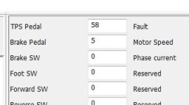
it didn't even change after i enabled motor temperature readout and the both share the same input pin. so it's a toggle. and it still showed 5 even though there is nothing connected to the input pin.
 
izeman I think I saw your over run or over rev issue today testing a different motor.
I had not updated the Pole count to the correct number and the first time I ran the motor (after autodetect) it would rev high then drop back a little.
Once I got the pole count correct it stopped happening.

I am totally NOT confident this is the same issue. I
 
thank you for the update. i'm afraid this is not the issue here. i noticed that changing the poles only results in incorrect rpm readings of the software. of course it is a parameter used by the controller's cpu. but at least for me it didn't make a difference if i changed the value from eg 32 to 16.
 
Back
Top