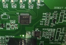
O2Micro OZ890 Based BMS Units

circuit said:
friendly1uk said:
I don't think they set my software as requested. I can't charge my lipo anywhere near the 4.2v hvc I specified.
Probably because one of your cells reached 4.2V and bms just switched off?

I wish it were that simple. There new cells, delivered to me very well balanced at around 3.65v each. They have spent less than 5 mins on the charger, which charged for 1.25 seconds, then standby 7 seconds, and repeat. This went on for a couple of mins then it just sat on standby. I could discharge them to prove what is happening, but I don't feel the need. I would rather just get them programmed properly.
 
friendly1uk said:
I wish it were that simple. There new cells, delivered to me very well balanced at around 3.65v each. They have spent less than 5 mins on the charger, which charged for 1.25 seconds, then standby 7 seconds, and repeat. This went on for a couple of mins then it just sat on standby. I could discharge them to prove what is happening, but I don't feel the need. I would rather just get them programmed properly.
Oh, so it looks exactly what I'm saying - one cell is hitting OVC condition. Maybe OV was set wrong, not to 4.2V, but still. This BMS is crap because it disables bleeding during OVC, so proper ballancing is impossible.
BTW, equal voltages on cells have absolutelly no meaning if that voltage is far from "full" (as in your case), so I'd recommend to re-check all voltages whem BMS goes into OVC. This way you will know what exact OVC is programmed.
 
circuit said:
This BMS is crap because it disables bleeding during OVC, so proper ballancing is impossible.
This is incorrect I have seen the voltage bleed down and the charger turn on and top off the battery. The one I have works great but again it maybe programed different.
 
There all 3.65v and the moment the charger gets plugged in they have 46.6v across them (3.884v each I calculate, not measure) so as to charge. This cuts the charger. I would say all the cells are hitting hvc.

I think the balancing occurs around half charged. Many people self balance every few weeks, so balancing every time you pass half charged should be ample. If balancing could happen at any time, then that might be about all it did, if a single cell was weak. Bike manufactures have to use these highly variable lipo cells and get a year out of them for warranty reasons, which this helps accomplish.

I should really measure the voltage at an individual cell during charging, but it seems pointless. There all at 3.65v individually and won't charge. I would need a very high cell resistance somewhere to be hitting 4.2v instantly. Something I would of hoped the manufacturer would of noticed when conditioning them for storage.

Has anyone got to the point where they can program these things, or are people just able to read from them? I need these fixing and I'm not looking for mates rates, Just somebody capable.
 
friendly1uk said:
Has anyone got to the point where they can program these things, or are people just able to read from them? I need these fixing and I'm not looking for mates rates, Just somebody capable.
I think you have limited options and none of them sound that great. If you want to stay with this BMS order a few boards and a programmer and hope the programmer does what you want it to do. If you have limited money use another BMS or just order another BMS like the one you have. If you don't care if you use a BMS just manually keep an eye on the cell voltages.
 
emiyata said:
friendly1uk said:
Has anyone got to the point where they can program these things, or are people just able to read from them? I need these fixing and I'm not looking for mates rates, Just somebody capable.
I think you have limited options and none of them sound that great. If you want to stay with this BMS order a few boards and a programmer and hope the programmer does what you want it to do. If you have limited money use another BMS or just order another BMS like the one you have. If you don't care if you use a BMS just manually keep an eye on the cell voltages.

I have been trying to do it different ways, but finding any lipo bms at all is proving very difficult. I have seen just one, that is for 16s, and I need to buy far too many.
I can't keep ordering more like the one I have. I have asked if they can be sure this time, but I have wrote half a dozen letters to them since my order was dispatched and they never reply as the order was a total shambles. I can't order from a company that won't talk to me. They have the programmer at half the price of anyone else, but I can't get one. If I did, it is usb and I have never had a usb device work on any of my pc's. I have to buy serial if I want things to work.
I could switch to lifepo4 as I guess that is how the bms is set, but guessing is no good. It is too low a voltage anyway.
I won't run without bms. I would rather face defeat than pretend what I'm doing is right.

I have one supplier (henry) getting back to me, but I can see his product is lifepo4 and his title says lipo just to waste peoples time. Nearly every lipo search comes up with lifepo4 stuff being wrongly advertised.

I'm having a day off from this. I'm getting blinkered. I can only see red.

Thank you
 
henry of Bestekpower will sell you a lipo BMS if you want. but don't go whining and insulting him because we have worked hard to develop a relationship with him so that he would sell us these BMSs individually instead of 10-100 lots at a time. this is the only source we have for lipo BMS so if you start harassing him he may not help us any more.

you already said you don't have any use for his products so just leave him alone please.
 
I thought the oz890 was capable of doing lipo? I'm close to taking the $130 hit for the pc link stuff. Are you telling me the oz890 can't do lipo at all?

Your last comment was insulting by the way. I have no interest in your opinions of me. As your telling me he is the only supplier, do you really think I'm going to take the slightest bit of notice what you say? Would you like me to just bin the entire project instead? Get a grip man. I'm having a righteous moan about people that have done things. I have no reason to moan at henry. To satisfy your concerns...

Friendly said " Where are the prices? "
Henry said " What prices you need? "
Friendly said " All of them? I can't see any at all.
I have a 12s lipo pack. I want a bms capable of 30Amps continuous. I would like it under 50mm wide to fit within a 2x2 (51mmX51mm) square tube. I see you have a two level board at 50mm that I could perhaps strip for bits. The 25A HCX-D132. The HCX-D141 might suit me better though, It is just 32mm wide and I could upgrade it or use a couple of them.

What chip is in these? I have a pair of oz890 boards from bmsbattery sold as there 5-13s smart bms. They didn't program them as promised though, and I have no way of doing so myself. I see your boards are adjustable. How are they adjusted?

Thank you

Richard"


You have some problem with that?
 
I use four of these BMS on 12s and 10s Lipo, except for the failure of my friend, who didn't connect the balancerleads correctly I guess, they always worked fine.

I check balancing frequently, all cells where always OK. NEVER lost ANY cell using this BMS. It's great IMO.

Does anyone offer programming of these chip's in the EU? In the UK would be nice. I don't think they set my software as requested. I can't charge my lipo anywhere near the 4.2v hvc I specified.

I can programm your BMS if you send it to me, no problem. I can also test charger, discharge and balancing functions, I have all equipment here to do that.
 
Hero Crossbreak!
PM sent! :)

Looks like I'm getting back on track. I also have two other suppliers that got back to me, But fixing what I have makes better sense.

Thank you all for your help. It's been invaluable. Even when I didn't want to hear it.
 
crossbreak said:
I can programm your BMS if you send it to me, no problem. I can also test charger, discharge and balancing functions, I have all equipment here to do that.
You are using the BMS battery programmer? I2C systems I have used in the past can loose connection. Because of this problem I am don't know if the system would be robust enough to connect to a microcontroller and display the battery condition reliably. I am happy with the BMS and it works great. I plan to order more boards for my bike projects. The pack I have now cuts off at around 4.2v. Did you look at your boards and notice how they configured the boards? If so can you share the settings?
Thanks
 
You see this smile? It was hidden under egg on my face :)

It seems the fact they didn't sort out the B+ to P+ connection through R1 left me plugging in the balance wires as if the chip was not powered up. Killing the board to some degree. I have now wired up the second board(found it didn't work)Then reset it and I have balance lights flashing for 4 cells(all from one pack). As I type, one has extinguished and another has started illuminating, Which follows reports here on es that it comes set from factory as 4 cells at a time. Now I have seen 6 different cells have a go at balancing, and charge voltage is approaching 50vdc.

It appears that they were programmed and the caps swapped, but B+ was not taken care of, so one died straight away. Also that the auto reset upon connection is not activated.


I actually expected it to stop charging while balancing, but the appropriate 39ohm resistors are cooking away, and the charger is still lit red and it's fan going.

All together I'm feeling much better, so sod the charging, I'm off out for a pint. It's a national holiday in the UK today :)
 
crossbreak said:
I am happy with the BMS and it works great.
Can you confirm that it continues to bleed high cells once HVC is reached and charger is disconnected?
At first mine did balance (when idle balancing was enables) at idle and while charging, but once HVC condition occurs, it switches off both charger and bleeding. Cells sag a bit on their own and then charging/bleeding continues. Eventually it gets to point where high cells do not sag on their own and it all gets stuck with charger disabled and cells not at balance.
Now, I can't get any bleeding at all and it looks like all voltage values are frozen, like ADC sampling is not working.

I do have the programmer from bmsbattery. I just can't get it running whatever setting I try. app shows chip version C0.

EDIT: I contacted BMSbattery customer support, Melody Wang. They offered free replacements with my next order. I am not going to order anything, so then they offered to pay for postage ($100). I said I am not going to send more money, so they were "sorry". I reminded them of 16 days I have for paypal dispute, so they have promised to send replacements for free. But I guess this is just to make me shut up until I run out of paypal time.

Is anyone planning to buy anything from them? They could add my replacements to your order and then you could re-send them slow&cheap to me (of course I would pay for it). I'm in EU.
 
yes I'll order next mounth ;) mine did bleed after shutdown the last time i tested. My software works fine :? which OS do you run? WinXP?

Adapter from inside:
View attachment 1
bmsbattery_I2C_adapter_2.jpg

Original settings for 12s
 

Attachments

  • BMS_battery_factory_EEPROM_Setting_12s.zip
    3.3 KB · Views: 183
Thanks. Will try to upload this EEPROM dump... After I figure out why most of the values are greyed out now and I can't edit them or upload new data.

EDIT: after numerous hard resets of programmer, BMS and app restars, I have managed to get access to registers and write default config. And wow, now it works! Balancing, at least (in idle). But I still get 111°C internal temperature... Also discharge current was -9 amps at first, then jumped to +88mA charge. Voltage on sense pins jumped too, so I guess this is hardware related.
 
Bargh. I can add myself to the list of idiots. Not checking there work was bad, but I just blew up the second bms. Shorted the charger wires on my final checks. The frog box uses an audio connector for charge input, and it's a round part in a round hole held by a single nut barely 2mm thick. Any twisting and it comes loose. On my last check before the lid went on, My snipes slipped off and bang. I thought these boards were short protected, but the fuse to the chip (a 10 ohm resistor) has gone, and I'm seeing just 8 ohms of resistance from the circuit with the fets taken out. That seems pritty dead to me.
 
sadly only the discharge output is short-circuit protected :x I feel sorry for your loss... but using klinke for current isn't a great idea, always use XT60/XT90, they are best.

EDIT: that was wrong. Your BMS should have shut down. There must be some other error.
In fact, It's the other way around: Both charge and discharge ports are shortcut protected. But only the charge port can stop current flowing into the battery. Overcharge due regen power through the discharge port cannot be stopped...the battery could be infinitly overcharged this way. This is why i always both discharge and charge through the discharge port (the other thing is that i only have one plug not two which saves me a lot effort and money). with the FETs this bmsbattery board comes from factory, it is limited to around 8amps continous. But this can be enhanced easily.
 
friendly1uk said:
Bargh. I can add myself to the list of idiots. Not checking there work was bad, but I just blew up the second bms. Shorted the charger wires on my final checks. The frog box uses an audio connector for charge input, and it's a round part in a round hole held by a single nut barely 2mm thick. Any twisting and it comes loose. On my last check before the lid went on, My snipes slipped off and bang. I thought these boards were short protected, but the fuse to the chip (a 10 ohm resistor) has gone, and I'm seeing just 8 ohms of resistance from the circuit with the fets taken out. That seems pritty dead to me.
Maybe the fets on the other board are good and you can move them over. Sorry you had this happen.
 
Made some discharge test with 5BMS, all with the same settings at 12s Lipo, using MasstechMS8229 and Turnigy Wattmeter as reference. Both Wattmeter and Masstech readings very similar. The 5 tested BMS all had current readings 5-10% below of what my two analysers measured. I will calbrate all BMS before I ship them in future. Sorry friendly1uk, I did not calibrate yours :( hope it arrived safely :)
Test working point 47.4V/22A

In the upper range (35amps and more) the readings became even 15% off with one BMS :x

Also confirmed the readings while charging with a Hyperion EOS-1420, looks like the turnigy wattmeter is quite accurate.
 
I have not redraw all schematic of this BMS, but it looks like there is no current measurement shunt, so it may be measured ridectly on open mosfet, using it as a resistor. Problem with mosfets is their thermal resistance stability - grows rapidly when hot.
 
Can I solder an external shunt?`

Did a second measurement with 44.2V/51.4A. The FETs get warm, but not hot. Guess this is ok without additional heatsink. Didn't write down the measurement, but it doesn't seem to be more accurate at this working point.
So bad I can't connect the TurnigyWattmeter to my desktop PC :( The only two devices that have USB plugs are the BMS and the EOS-1420. I'd like to log the data of both and compare it in an excel sheet, would be so much better than using pen and paper :x

EDIT: I'd like to use my BMS with 90amps. The IRFB4410 can do 88amps at 100°C, 380amps impulse current. I ask myself if it would be safe to use it with these original FETs, since there are 3 conducting parallel :?
 
crossbreak said:
Made some discharge test with 5BMS, all with the same settings at 12s Lipo, using MasstechMS8229 and Turnigy Wattmeter as reference. Both Wattmeter and Masstech readings very similar. The 5 tested BMS all had current readings 5-10% below of what my two analysers measured. I will calbrate all BMS before I ship them in future. Sorry friendly1uk, I did not calibrate yours :( hope it arrived safely :)
Test working point 47.4V/22A

In the upper range (35amps and more) the readings became even 15% off with one BMS :x

Also confirmed the readings while charging with a Hyperion EOS-1420, looks like the turnigy wattmeter is quite accurate.

I'm not sure what your saying pal. Do you mean a 30 amp bms, working at 30 amps, might think only 27-28.5 amps are flowing? I'm not sure what relevance this has. Is it related to currant limiting?

I'm not sure what currant limiting they do. If I were to try and hold the 60 amps max, would it heat the fets, see the currant is too high, and actively throttle it back to 30 amps again? Thus it needs to be accurate or it would reduce down to 28 amps?

I should I read more shouldn't I...

Nothing from the postman yet. Perhaps tomorrow.
 
Back
Top