O2Micro OZ890 Based BMS Units

I get it now :) The board delivers 5-10% more than the written specification. Playing if safe really, as it would be unfair to not reach specification. With the voltage across the fets used to calculate currant, heating of the fets would trim that 5-10% down to a lower tolerance.

I don't intend to approach the 60 amp limit, So I guess this inaccuracy will never effect me :)


Post just arrived. Nothing yet. Can you PM me a tracking number, I'm itching for it.
 
PM sent! That's what sucks with the 4s hardpacks, they are only 46mm wide, but the BMS is 50mm :x have to make a proper enclosure and some new circuit board for the balance plugs. These Hardpacks arent that hard. a 6x4s brick fell on the floor from my desk, the hardcase on the edge got damage :x dooh! Still great for the price. Oh I forgot, my flor laminate has a 3mm deep hole now :(
 
crossbreak said:
sadly only the discharge output is short-circuit protected

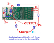
that wrong :x if one takes a closer look on the PCB, one can see that current flows through the discharge FETs if the charge leads are shorted
 

Attachments

  • short circuit current flow.png
    short circuit current flow.png
    96.8 KB · Views: 2,779
you are right. had not thought this through but if the pack shorts in any way then the current has to return to the battery through the shunt resistors and the processor will see it as the Delta voltage on the shunts and turn off the output mosfets to stop the current flow.

if the charger is active it could have the charger leads shorted and supply power to the short up until the charger fuse blows.

if the mosfets themselves then fail and short out there is little or no protection other than having the shunts themselves separate from the pcb when they overheat. those surface mount resistors may crack and open under the stress.
 
Shorting the charger port on mine caused R17 to blow. The resistor that carries power to the chip. I tried to bypass the resistor with another, and there was a little smoke and some balancing lights came on. They stayed on while all cables were disconnected except for the balance wires. It was the battery pack lighting them up through the balance wires. That was one pretty fubared board from shorting the charger socket. No charger present.

Thanks for the PM explaining the 10% over read is a problem when charging. IIRC the board is 10A rated for charging, so if a 10 Amp charger was used, an over read of 11 would cause the bms to disconnect.
 
the current limit during charging is related to expected current carrying capacity of the charging mosfet. most of us have pushed more current than spec, but sometimes the charging mosfet will burn up that way.

but the overcurrent protection is from the shunt current causing the BMS to shut off the output mosfets and the current flowing through the charging mosfet could burn out the mosfet and short it but if the output mosfets turned off then the shorting current would be interrupted but the charging mosfet would be toast. repairable but at least the short is stopped.
 
If you still got problems with your board like overcurrent shutdown during charging, just send it back to me, I have now experimented more with these boards and think I know how balancing works. You have to set idle and external balancing flag IMO. I will test further and will upload my settings when I am happy with the behavior. I will then upload some discharge, charge and idle balancing graphs with my favorite settings, maybe we can work together finding these. I can now also calibrate current readings of the BMS since I soldered a precise 10mOhm 14AWG wire shunt for calibration.
 
The charge fet seems fine. I'm going to send both boards over to get looked at though, So we will have a second opinion at some point :)

I'm happy with my board from you crossbreak. I once saw a slightly higher finish voltage of 50.6 but 50.4 every other time. Must of charged it 20 times at least, and the odd behavior was about the 3rd one, and the first decent discharge (4.2Ah while previous charges were just 2 or 3 Ah) so it was perhaps balance related.

I just had some odd behavior. First time I have hit lvc. It was not a clean stop, but rather a few stutters. I expected my watt-meter to be off, but that little bit that drains through the fets was sustaining it at 11 volts. I had used 4.6Ah of my 5Ah pack. What I found odd was it would not charge until I disconnected the watt-meters load. Easy for me as I have a key-switch between pack and watt-meter, but not so easy for others, and I have to wonder that if a watt-meter than consumes almost nothing can stop it charging, then would a motor controller? because that would be rubbish...

My meter has a consumption of 20mA in battery check mode. I imagine it is similar in watt-meter mode. Generally they quote maximums, so I would hazard a guess at under 20mA. It certainly didn't pull the leakage voltage down by much. I have used two digital volt meters, one pulls the 44v down to about 40v and the other pulls it down to 22v. It is quite easy to pull down.
 
I have used two digital volt meters, one pulls the 44v down to about 40v and the other pulls it down to 22v. It is quite easy to pull down.

Looks the same for me. I yet had no issue with stuttering motor. But I use 37V LVC in controller, so I might just not see that. Hope I can replicate that error on my test bench and see where it comes from.
 
Can someone confirm balancing works during OVC condition? I have four OZ890 based BMSes and all of them switch off balancing once OVC is reached. After few such cycles it causes cell voltage to stay above OVC release threshold and fail to balance or complete the charge.
 
Good morning, Crossbreak!

This is so strange because this unit was in service like that!

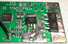
Both units I got (from another member here) had this short.

I have not yet hooked up any of them.

I see in some pictures from others that the gate pin is free, but some have the same short like mine, disabling any discharge control.

I have to reverse the layout and find out what is going on there. It simply cannot function like this.

Crossbreak, you seem to know these units quite well: where is the shunt?

It is the mentioned FET, is it not?

Thanks!
 
it would help if you just used the ohmeter to test continuity between gate and source. you should see a 5MR resistance. using a picture is not the way to actually prove it is shorted.
 
Strange that it works like this, it shouldn't... dnmun's tip should be quite useful

the shunt is the three discharge FETs. this leads to some very strange readings if the FETs are turned off, like 1000amps withtout anything connected... not remarkable, since shunt voltage is in the region of battery voltage in this case :mrgreen:
 
And I thought the shunt is the single FET!
And that that single FET is the discharge FET.
And that the others 2 or 3 parallel are the charge FETs.

All collapses. Really need the schematic, hope Methods would kindly enlighten us with his findings.

Yes, as mentioned in other threads, I did check, source and gate are really really shorted on both of my boards.
One is even shorted from below, quite deliberately so.

But folowing some basic traces I am now positive that this could have never worked as is.
 
no, you don't need the schematic. all the BMSs are wired the same when they have a separate charging mosfet like this one.

the drains are tied together usually end to end.

the source of the charging mosfet is connected to the C- spot and goes to the charger negative.

the source of the discharge mosfets is tied to the current sensing shunt wire and through that to the B- spot and from B- to the negative terminal of the battery.

P- is connected to the drains.

the mosfets will all have a pull down resistor between source and gate. it will be about 5MR. you should see that when you measure with your ohmeter.
 
Thanks, dnmun
I had no opportunity yet to remove the short, so I cannot measure the resistor you are mentioning yet (it needs a strong soledering iron).

I do see some 1MOhm resistors there (in accordance with OZ's schematic) on the board.

Will report back when I desoldered the shorting blobs.
 
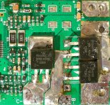
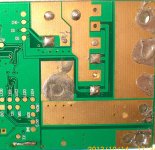
Some hi res pics.
On this board I corrected the SmartBMS "open power cap issue" by placing a wire through the via and soldering it to the open side of the cap.
That cap can be seen on the top left corner (C4) and the via on the bottom left of the lower picture.
SmartBMS_shorted gate_top01.jpgSmartBMS_shorted gate_btm01.jpg
 
CG is gate for charging fet, DG is gate for discharging fet. Z2 is the zener on the gate/source and the R23 next to it is the gate pull down resistor for the charging fet.

it looks like someone just put a huge gollop of solder on the charging source ground plane and shorted the gate by negligence. someone has already stripped the third discharge mosfet off the pcb. duh?

poor workmanship by the guy you bot it from. he ruined it and sold it to you i guess. so that may be the only thing wrong with it and why it doesn't charge.
 
I cleaned up the third FET area.
It was slightly covered with solder. There was no FET, the original purchaser probably ordered the low amp version which seems to have 2 FETs only.

I thought the charge FET is the discharge FET, thus the question about exchanging them in the other (shunt) thread.

The huge solder blobs causing the short are a few mm high, they were there when I got the boards.

Will check the FETs once I removed the solder, it may be that the boards were fried by him, don't know.
 
So I got one of these SmartBMS finally working and hooked up to the PC and it and it looks cool, the voltages being reported and all.
Really nice!
Did some EEPROM changes Crossbreak recommended (set #13, SC Delay to 256uS), also set LVC to 3.55V and HVC to 4.1V and their appropriate limits to 50mV.

What I still don't understand is how is the discharge current measured on the SmartBMS board??

I understand that the single FET is the charge FET and they measure the charge current via it's RDSon, but what about the 2 (or 3) discharge FETs which are in paralell?

The OZ890 has only one current sense input and the discharge FETs are (onviously) not in that path!

Also, I noticed what has been mentioned here, that the unit stops totally when the HVC is reached, no balancing goes on after that.
How did you guys solve that?
Thanks!

Edit, found this
http://endless-sphere.com/forums/viewtopic.php?f=14&t=20971&start=125#p792853
Is this what Crossbreak was toalking about?
 
yep, this is what I talked about. Still:
circuit said:
I have tried that option, id does bleed in idle. However it does not in OV state, so balancing takes forever. Maybe different chip revisions?... Probably it is a known bug in the chip, but it is not like we can get an errata sheet...

:evil:

This bug could be caught by setting some register while this bug appears, to re-enable balancing. an attiny25 has so low power consumption, it could be supplied by the onboard 3.3V rail. Additionally it could log some data


The OZ890 has only one current sense input and the discharge FETs are (onviously) not in that path!
there must be some path, how can it measure current otherwise?!?
 
Back
Top