one more try at sorting out this flaky motor issue ...

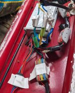
sorry about that link and no throttle there. my brain is on high fritz. will try to find it. meanwhile, i'm pretty sure i have the bench test set up correct but have a look at the photos and let me know. if it is right, with power on, moving the throttle lever produces nothing. meter stays at zero. i dunno. i must be doing something way wrong.

black ac wire twisted to black throttle wire.
red ac wire twisted to red throttle wire.
green twisted to nothing.

isn't that the same as the guide diagram?

if i hook the probes up to black and red, i get the expected 4.9 v. but if i hook them up to black and green, i get what you see.

found throttle i bought: https://www.amazon.com/gp/product/B07JYYQ38H/ref=ppx_yo_dt_b_search_asin_title?ie=UTF8&psc=1
 

Attachments

  • PXL_20241002_170003466.jpg
    PXL_20241002_170003466.jpg
    2.5 MB · Views: 5
  • PXL_20241002_170108119.jpg
    PXL_20241002_170108119.jpg
    2.1 MB · Views: 5
  • throttle-test-off-scooter[1].png
    throttle-test-off-scooter[1].png
    74.6 KB · Views: 5
Last edited:
Hey, no worries about the throttle info. Your latest link was most helpful, and everything looks good.

Your wiring and testing looks good and would indicate a bad throttle except for…. :mrgreen:

But if I could talk you into taking the block connector out of the equation totally, just to be totally sure.
Which would be as easy as taking the voltage readings from the other side. The side where the wires enter the connector.
Meter probes direct to the bare wire ends… removing them from the connector if needed, for access.
Of course you’re still looking for .8dcv with throttle in home position. (No twist) To ~4.2vdc WOT.

That should nail it down directly, till we go to the internal parts and wiring if desired. :D
 
yep, i did that and got the same darn results. maybe the easiest thing at this point would be to buy a new throttle. can you see (an inexpensive) one on amazon that might do the trick, given that the one i bought before is out of stock?

meanwhile, i might just take the existing throttle apart and see if something obvious is wrong ...

update: this one look okay? https://www.amazon.com/Electric-Acc...&sprefix=ebike+thumb+throttle,aps,155&sr=8-14
 
Last edited:
Ahhhhh, you’re way ahead of me…. well done!

The replacement you found looks good. .5 mm off in difference of handlebar diameters, but I would think that would be close enough.


meanwhile, i might just take the existing throttle apart and see if something obvious is wrong ...
Sounds great.

Also try that battery for the throttle hack to make sure the controller is working…
 
best to get a new one ... after what i did to the old one, getting it apart. in any event, not much to see inside! delivery is tomorrow. i will be back, if'n there's nothing else for me to mangle in the meantime.
 

Attachments

  • PXL_20241002_210819706.jpg
    PXL_20241002_210819706.jpg
    2 MB · Views: 2
Sounds like a good plan.

I’m a bit wary wondering why you are going thru throttles…? Unless you know why, perhaps take voltage readings on the 3 throttle wires coming from the controller BEFORE you wire up the new throttle.

Otherwise looking forward to a successful repair tomorrow!

EDIT: Hey, while I thinking about it. Disconnect the 2 single white wires for unlimited speed if desired.
 
Last edited:
okay, i took the v readings on the controller's 3 throttle wires:

1/ red and green: 4.7 v
2/ red and black: 4.71 v

i believe those are happy numbers, right?

and now i await the new throttle and then we shall see what we shall see. any precautions i should take before i wire the thing up?

should i do the test with the 3 v battery first?
 
1/ red and green: 4.7 v
2/ red and black: 4.71 v

i believe those are happy numbers, right?
Looks good to me. Thanks for checking.
I think your good to try the new throttle.


should i do the test with the 3 v battery first?
It wouldn’t hurt, but may be more hassle than what it’s worth… totally up to you.

It would be like using an on off button for a throttle. And to see what that involves, see this thread.
Using an On/Off-Momentary Push Button Switch that’s normally open to replace a hall throttle.
 
well, i am distressed, not to mention depressed, to state that the new throttle changes nothing. same results as with the old one. i even went through and made all the connections wire to wire with no couplers. i am at a loss.
 
Rats!

Post some throttle voltage tests, let’s see what’s going on and possibly eliminate the throttle as one of the problems.
 
will do. i'll go back through everything. did the 3v battery test and the wheel turned at the same speed it always has. sigh. maybe i'll take the trike out for a spin to clear my head ...
 

Attachments

  • PXL_20241004_212931227.jpg
    PXL_20241004_212931227.jpg
    4 MB · Views: 3
You might want to see if the 810LED works. Put it in walk mode ad see if motor turns, Also, if your scooter has e-brake levers with switches, make sure they are not closed.

You can also easily check the 810LED with a voltmeter. As your seller told you, it puts out a DC output voltage for the 3 PAS levels and the walk mode, If you show a pic of the 810LED connector, I can tell you which wire to look at, It's not hard to test.

However, it should have four wires. Two are battery power and ground, probably red and black. A third wire is probably blue, It's 0V until the 810:ED is turned on,. Then it goes to battery power when the 810 turned on. This powers up the controller, The final wire is the output, and is a green wire on my 810LED connector, It will have the following voltages,
0V Off
1V Pas 1
2V Pas 2
3V Pas 4
4V Walk mode
 
doc: thanks for weighing in. i got all the right voltages as i went through the PAS levels. i got 4v for walk mode but walk mode itself does not lock in and turn on the motor. that 4v lasts only as long as i keep the button pushed.

sign me, discouraged.
 
That says the controller got cooked, or maybe it was originally a self learning controller. Those controllers have a pair of wires you connect during a power up, and the unit figures out how the motor wires were connected. If all goes right, the wheel spins a few times, you disconnect the wires, wrap them up, and the controller should remember those settings,

Your pics show a bunch of wires cut off.
 
i cut all the wires down at some point because they were too confusing. didn't think in my case i needed to do the white wire self learning. i'll see if i can't reconnect the white and go from there.
 
As you are using a BLDC motor without hall sensors, I don’t think a learning wire would help much in your situation.
But from your controller description webpage, the white wires are for a speed limiter. Not a learning wire…
Unless your manual states differently.

The walk mode operation check is a great idea. It’s my understanding that it is only operational with the button being pressed…

Good have you back at it after the set back. Hoping your new throttle is still viable with some good voltage results.

As far as not ramping up…

With no power going to the controller, does the motor wheel have resistance or clogging when you turn or spin it?
If so, does the resistance go away when the 3 main phase wires are disconnected from the controller?
 
The motor cable is at the top of the screen. Looks like a bunch of wires cut off., so I think it was a sensored motor.

PXL_20241001_173558186.jpg
The diyebikestore.com website listed on the controller label is still in business. They sell a few low amp controllers that use the 810LED, but none are sensorless.

I would just spend the 25-50 bucks and buy a new controller, restore the notor cable, and scooter on,
 
at the ebay link to the controller i bought on ebay, the specs say this: "It is compatible with sensorless and hall sensor motor." your link shows the same thing. am i reading what that quote means wrong?
 
No. I didn't see that statement about sensorless on the web page. Why put Hall connectrs on a sensorless controller was my thought, No learning wires on those controllers by the way.

Anyway, if Walk mode won't work, and the motor used to work with the same connections, the controller must be blown. They don't appear to be expensive.
 
tommycat: with no power going to the wheel, there is slight resistance with the wheel spinning backwards, none going forward. with power on, the resistance amount is the same. with the power off, i connect the phase wire to each other and there was major cogging backwards, nothing forward.

with the throttle removed, red and black at the controller returned 4.72 vdc

with the throttle connected, red and black = 4.35 vdc
-- green and black: .872 vdc resting and 3.54 vdc with throttle a max.

doc: i guess they put hall connectors because the controller is supposed to work with both types of motors.
 
Last edited:
tommycat: with no power going to the wheel, there is slight resistance with the wheel spinning backwards, none going forward. with power on, the resistance amount is the same. with the power off, i connect the phase wire to each other and there was major cogging backwards, nothing forward.
EDIT: With no power, motor disconnected, and phase wires separated. Same as the first two checks.

Sounds like a geared motor with clutch…
Any chance it’s just running backwards? I know you tried swapping the phase wires around… but did you try to swap just two?
This would change the direction.

with the throttle connected, red and black = 4.35 vdc
-- green and black: .872 vdc resting and 3.54 vdc with throttle a max.
Relieved to see this. :)
 
Last edited:
well ... i messed around with the phase wires and now ... the motor is getting no power at all. i didn't quite understand your directions, so i went blithely forward and can't quite recall what i did with the phase wires but now i can't get any cogging whatsoever, not to mention any movement out of the wheel or sound from the motor. gak.

p.s. i checked the throttle and i'm still getting power there ...
 
Last edited:
Well, just trying some quick tests that would show if your motor phase wires are sound. Or if the controller fets are damaged.
Saw some poor connections on your phase wire connectors. (Stray wires… clean those up.) Check for good contact thru those bullet connectors also.

But no cogging is actually a good thing.

Just double checking the motor at this time before possible controller replacement.

See this thread for in depth instruction on checking your motor’s wiring. With your steady advancement of skills, perhaps you may want to try and repair the motor’s hall sensors for the best performance. :giggle:

Testing BLDC motor's Phase Wiring - Hall Sensors and Wiring. - Electricbike.com Ebike Forum

Double check all connections. brakes off, battery charged. What voltage are you running?

If I don’t make myself perfectly clear, by all means call me out on it before experimenting.
 
Easy way to find out if it's. A bad throttle is down an ohms check out Ur meter to ohbs seev if the resustance changes if I dose then
In put the probs on the wiresv and twist the throttle
 
Back
Top