Open Source CA alternative on German pedelecforum available

crossbreak

1 MW
Joined
Aug 2, 2011
Messages
2,889
Location
Germany
Hi guys,

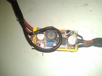
the members of my local ebike forum have developed an alternative to the CA with a lot more functions, using the Arduino Nano as a base. I try this myself since a few days, and while crawling the net for code, I came across this. It's called the "Forumscontroller". There is a common PCB shield that can be ordered from the user " jenkie" if you have a pedelecforum account. The code is available here: https://github.com/jenkie/Arduino-Pedelec-Controller

some specs can be read here: http://www.pedelecforum.de/wiki/doku.php?id=elektrotechnik:forumscontroller

planed/realized functions: ( can't tell, didnt read all threads yet)

-Voltage: up to 60V, Current +/-30amps, and a lot more for both if customized
-headlight output
-throttle and regen mapping, current mode throttle control
-battery and phase current limiter
-PAS and pedal torque sensor (by Thun)
-antispark circuit
-LVC
-bluetooth I/O
-speedlimiter
-elevation sensor
-soft start
etc...

Supported Displays:
almost all Arduino compatible displays, including old Hitachi compatible parallel types, Nokia phone graphic displays etc...

Since I lost overview, has someone posted this here yet?
 
crossbreak said:
the primary aim was to meet the restrictive German laws for e-bikes. There is both a power and a speedlimit.
why? as it's only 60v and 30a ... ;) *scnr*
in austria we have ebike limits as well, even though they are not that strict. 600w and 25km/h w/o pas.
 
[...] tiny5 microprocessor on the PCB [... ]Anyone on here looking to make something of this type want to do some programming.......????

WTF? bobc, plz read the first post in this thread, you will see that the Germans already did all programming for us. Just buy a Arduino Nano. No need to connect a display to the Forumscontroller.

If you want to build your own and write your own controller hook software plz dont hijack this thread for your topic. There is this kind of standardization now, why not use it and start from zero? It would be nice if you could write an ESC library/extension for the Forumscontroller base software, then the others here would benefit from your work also.

why? as it's only 60v and 30a ... *scnr*
The German manufacturers usually use 36V/14amps, so the unwritten limit here is 30kph@500Watt, almost the same as n Australia. But the throttle can only be used till 6kph, after that one has to pedal.
I will come up with an own PCB and some software changes, to make using 75amps max possible, there is no law against it if you drive through the woods.
 
I've got a small throttle issue: The input value sometimes jumps from 206 to 222, even if I do not engage it. Solved it by raising the "zero" value to 222, but loose a little throttle resolution. Maybe I need some noise supression here? Anyone tried it yet?
 
What I want from this module what the CA cannot do:
-show all info I want on one screen without any need for switching
-analogue speed and motor rpm gauge
-I2C interface to my BMS
-Throttle remapping, phase current control - important when using a middrive. This way I can squeeze out what my gearbox really can do.
-Street legal drive mode with very fast PAS sensor response - important when driving on German roads.
 
I now chose the ACS758 bidirectional hall sensor for phase current sensing, the one that fechter suggested. Typically the PWM frequency of BLDC controllers is below 20khz, so this should be the right one, it has a 120khz output bandwidth. Next step is signal processing, I need to now the duty cycle, the field change frequency (=electrical rpm of the motor) and the RMS current. This can not be calculated by the arduino it self i guess, since it is to slow. I haven't found out yet how fast the loop will be, so I wanna go the safe way and make a daughter board that simply outputs these three values.


e-rpm should be quite simple using one schmitt trigger, one capacitor and one resistor. Any suggestions how to implement a duty cycle analyzer and the RMS current analyzer?
 
I found this reference: http://arduino.cc/forum/index.php/topic,6549.0.html
It says that in standard config, the max sampling rate is 9600 Hz. Which is too slow :(

This can be speeded up using a different prescale factor.

My main aims for the motor-controller hook up baord are:
*measure the duty cycle
*measure RMS phase amps
*measure e-rpm
and of course battery amps and voltage, but that seems to be quite simple.
 
controller hook v1, reads

battery voltage (voltage devider, 100 kOhm and 10 kOhm, white wire) and
current (ACS758, green wire), and
outputs 5Volts (red wire) for the Arduino (LM2596HV converter, input 60V max)
 

Attachments

  • controller hook1.jpg
    controller hook1.jpg
    68.9 KB · Views: 7,752
  • controller hook3.jpg
    controller hook3.jpg
    79.4 KB · Views: 7,752
crossbreak said:
I need to now the duty cycle, the field change frequency (=electrical rpm of the motor) and the RMS current. This can not be calculated by the arduino it self i guess, since it is to slow. I haven't found out yet how fast the loop will be, so I wanna go the safe way and make a daughter board that simply outputs these three values.


e-rpm should be quite simple using one schmitt trigger, one capacitor and one resistor. Any suggestions how to implement a duty cycle analyzer and the RMS current analyzer?

I know Analog devices makes a RMS to I think DC voltage converter to get around the math or do a sum of squares to do RMS. This may have to be done in assembly.
If I can remember this microcontroller is just a 16 mhz chip, you may have 800 tcycles per motor rotation to do all tasks on the bike if erpm is 20000. I just had the kit come in and need to get the processors and the display and read more on the processor architecture and the code. It's RISC so that should help. You can't do the duty cycle with a timer?

Steve
 
emiyata said:
I know Analog devices makes a RMS to I think DC voltage converter to get around the math or do a sum of squares to do RMS.
This one?
http://www.analog.com/static/imported-files/data_sheets/AD536A.pdf
 
amberwolf said:
http://www.analog.com/static/imported-files/data_sheets/AD536A.pdf
Wow It looks like the one. The one I have is in a different package style. I assumed it was discontinued with microcontrollers so cheap and powerful they calculated this way, say that you sample the current (or potential difference) at tiny intervals of time. Square each value, add up the squares (which are all positive) and divide by the number of samples to find the average square or mean square. Then take the square root of that. This is the 'root mean square' (rms) average value.
 
crossbreak said:
I found this reference: http://arduino.cc/forum/index.php/topic,6549.0.html
It says that in standard config, the max sampling rate is 9600 Hz. Which is too slow :(

This can be speeded up using a different prescale factor.

My main aims for the motor-controller hook up baord are:
*measure the duty cycle
*measure RMS phase amps
*measure e-rpm
and of course battery amps and voltage, but that seems to be quite simple.

Can you just cheat by not measuring the phase amps, but calculating them instead. Downside is you would need to enter/measure some basic motor specs, but then you just need battery amps and speed to get a half decent ball park phase amps. If you are just trying to do torque control via throttle over-ride this might be enough, it is not like you can actually clamp phase spikes as you don't have direct control over the FETS.
 
this is reasonable for a known motor. I can just simulate it using ebike.ca calculator and use a polynomial to approximate the phase to battery current ratio for a given motor rpm. This way I can get a realatively flat torque curve and can implement a torque throttle, which are my primary aims.
 
Ok, I made some experiments reading battery current with ACS758. Seems like the best accurate analog resolution I can get from Arduino is 8 bit @ 800 Hz after noise filtering. That means within my 200A current range I get 200A/2^8=0.78A per step :( That is more than the no-load consumption of my ebike at full-throttle!

Looks like I need better hardware even for reading just the battery amps. I read that Teensy 3.0 http://www.pjrc.com/teensy/index.html using ARM Cortex M4 gets about 13bit @ 2200Hz real life resolution after noise filtering http://forum.pjrc.com/threads/407-Teensy-3-0-ADC-details
That would be 0.025 A per step, which seems accurate enough.

The board that casainho uses http://endless-sphere.com/forums/viewtopic.php?f=3&t=38337&start=105#p682893 has 12bit resolution http://www.bravekit.com/STM32F100_HB_development_header_development_board_JTAG_ARM_CORTEX_M3 Datasheet http://www.st.com/st-web-ui/static/active/en/resource/technical/document/datasheet/CD00251732.pdf, so in real life this should be 10bit, which means ~0.2A per step which isn't as accurate as I would want.
 
crossbreak said:
Ok, I made some experiments reading battery current with ACS758. Seems like the best accurate analog resolution I can get from Arduino is 8 bit @ 800 Hz after noise filtering. That means within my 200A current range I get 200A/2^8=0.78A per step :( That is more than the no-load consumption of my ebike at full-throttle!

Looks like I need better hardware even for reading just the battery amps. I read that Teensy 3.0 http://www.pjrc.com/teensy/index.html using ARM Cortex M4 gets about 13bit @ 2200Hz real life resolution after noise filtering http://forum.pjrc.com/threads/407-Teensy-3-0-ADC-details
That would be 0.025 A per step, which seems accurate enough.

The board that casainho uses http://endless-sphere.com/forums/viewtopic.php?f=3&t=38337&start=105#p682893 has 12bit resolution, so in real life this should be 10bit, which means ~0.2A per step which isn't as accurate as I would want.
Remember just because you have a 13 bit ADC you maybe just getting numbers not more accuracy than a 8 or 10 bit converter due to noise issues. Fix the noise issues first. The shuttle control system ran on 8 bit Z80 processors and worked fine. I always ask my self what am I going to do with this data and do I really need it?
 
I really need 12 bit resolution. I want to use batteries with down to 250Wh and I can not measure coulombs if accuracy is below 0.1A. But this is a good point, i really only need this resolution for battery voltage and current, for the rest 8bit is ok. Even phase current does not need to be that accurate. Only for RMS / duty cycle measurement I would need fast sampling rates, but I can still use that IC which emiyata suggested. But I wont even need that if I just estimate the motor behavior or input it as a polynomial spline .

I really like the Teensy 3.0. Small drawback is that ADC and DAC use 3.3V max . The only thing that needs more than 3.3V output are BLDC eBike controllers and halls. Guess that RC ESCs work fine with 3.3V, but eBike controllers need 4.0V as max throttle output (full-throttle) :( If this stays the only thing that needs higher voltage I'll switch to Teensy 3.0 or at least to an ARM Cortex, since it has better ADCs and it costs the same.

I checked all this peripherals and they fine even with 3.0V:
-hall throttle
-ACS758 hall current sensor
-PAS hall sensor, I also use them as tacho sensor for both motor rpm and wheel speed
-LCD screen
- RC ESC, if I read the right source. They are even better since they have more or less direct PWM duty cycle throttle (I'd love to have that on eBike controllers)


These things need 5V:
-honeywell SS41 digital hall sensor (used measure rotor postion of BLDC motors), maybe I can substitude them. Not necessary for a hook-up controller, since commutation is done by the BLDC eBike controller
-throttle input of KUxx controllers

The best thing would be a universal 5V->3.3V I/O converter :lol:
 
emiyata said:
Fix the noise issues first.
I even get this noise if I just connect one resistor to ground and one to +3.3V. I added a 22µF capacitor to make sure that input is REALLY only stable 1.65V. Still jumps around. I grounded all other analogue Inputs. Still jumps around. I added 20ms delay between the readings. Still jumps around :( I can only assume that this is just normal and cannot be solved at all :?

BTW, the Teensyduino has 16bit resolution, it's only 13bit in real life ;)
 
I would start with tantalum caps that has low esr or low esr electrolytic caps to snub hf noise. Shield your power wires ground just one side. If you have a scope see if it is high frequency . My bet it comes from the controller. Big caps don't snub HF small caps with low esr rating and very close to the source should fix it.

crossbreak said:
emiyata said:
Fix the noise issues first.
I even get this noise if I just connect one resistor to ground and one to +3.3V. I added a 22µF capacitor to make sure that input is REALLY only stable 1.65V. Still jumps around. I grounded all other analogue Inputs. Still jumps around. I added 20ms delay between the readings. Still jumps around :( I can only assume that this is just normal and cannot be solved at all :?

BTW, the Teensyduino has 16bit resolution, it's only 13bit in real life ;)
 
The datasheet for the ACS758 recommends a 0.1uf cap between VCC and ground (no resistor) - see page 5 of the datasheet. This should be a ceramic type capacitor, which is cheapest and also best for high speed applications. If the datasheet recommends a 0.1uf cap, the I'd say this should be your first step in trying to remedy the problem :wink:

I don't believe you will need a RC filter at all on the analog output of the ACS758, as it appears to be constructed using operational amplifiers not PWM type output.

I have struggled with noise on my recent push button throttle build, I found that a combination of 0.1uf, 22uf (both ceramic for high speed) and 220uf (aluminimum type, slower but larger buffer) capacitors have helped my application.

A google search for decoupling and / or bypass capacitors result in documentation of many people's experience of pain and anguish when dealing with stable analogue measurement :roll:
 
It turns out that I unintentionally lied in my previous post, you may need an RC filter on the output line too... I missed the big drawing on the front of the datasheet!!

ACS758.jpg

Unfortunately I'm not capable of recommending resistor or current values, I wish I could :( My understanding is that you should calculate the frequency of noise you want to reject, i.e. take the sampling rate (the number of times a second the arduino polls the current sensor), invert the value to give the sampling frequency, divide it by 4, then run the frequency through the following calculator to give you suggested R and C values...

Calculator

Perhaps someone here can recommend R and C values for the filter? The breakout boards for the ACS current sensing chips use capacitors and a resistor, it's just not possible from the google image search I've done to determine the C values....

Thanks

John
 
Back
Top