Quadcopter Build

Okay So I wanted to report on whats been happening with the Hexacopter carbon tarot frame.

I simply do not like it.
looks nice, but I do not like it.


I had a hard fpv landing and broke the Horizontal landing feet. I repaired it but I do not like it.

I have also experienced less range with the carbon frame.. I do not like this one bit, I had a moment where I lost about 1 or 2 seconds of control which seems like heaps when doing fpv. Luckily the transmitter gained connection and I bought it back to land it.
Overall fpv range was also less


This has never happened on wood/nylon/plastic frames, I normally never ever run out of reception.
I was thinking maybe I damaged my receiver.. did a range test seems fine. So it must be the frame and certain angles...


So tonight I have changed back to the quad frame.. ..
So its.. 8000mah.
fpv camera.
fpv transmitter
gopro camera


I have built so many of these things now.. does not take long.. its like building a computer
 
i ordered a q450 frame, 1100kv 3530 motors, 10" props, 9xr remote and a multiwii with gps and bt. really looking forward to building it. can't wait to see how hard it is to fly them. or even make them lift off.
all this programming stuff (flight controller, motor controllers, bt, radio) is so massive that it will take ages to understand it.
has anyone found a good noob's guide for someone who has never flown a helicopter and knows nothing about pitch and rudder etc?
price of parts was significantly higher than a rtf sk450 model but i hope my components are 'better' and more powerful. i don't like to buy cheap just to pay double the money for the second try. overall it was like $350 shipping included.
 
that will be a really solid machine!!!! you will be able to make it either an acrobatic machine, or use it as a FPV racer, Or a slow flying Aerial Video platform with a big 8000mah battery @3s

the 3530 motors are so good, the 1100kv version.
They have worked flawlessly with different quadcopters, hex, tri that i have tried.
8000mah got me like 16mins 1.7kg
4000mah about 11 mins @ around 1.5kg

What esc did you get?
( you cant plug all the ESC + and - into the flight controller, For example the Afro ESC has a Linear bec, you can plug them all into the flight controller.. Some others have a switching BEC's, you cant plug them all in at once, they will fry your flight controller... thats about the only thing you need to worry about doing.
Never reverse polarity anything tho.
 
Don't worry..

You got the best esc/motor combo for your first.. all have matching bullet connections to make it an easy fast build and easy to get the right motor orientation when firing it up

Your esc's can all be plugged into the flight controller, just make sure you do the right polarity... ( the afro esc you got have Linear BECS not switching, so they can all be plugged in for now with no issues)
Best to twist the 3 wire cables that run to your flight controller, Twist them and then plug them all in, they will supply about 2 amps of current to the flight controller all up, which will run your bluetooth module and gps.. and it will even run 2 servos if you want to in the future. two micro ones.
I think your esc's bec's put out 500ma each
 
I tend to fly more FPV now. I have found its faster to learn than 3rd person. And I enjoy it alot more...


A few things I have found to make it a more enjoyable experience for video feed..
-Pick a good place for the ground station/where you sit. dont have tress or any objects around you at all.. even a few meters away that it could potentially distort your video feed.
You want to try get a line of site of the area you want to fly, try sit yourself in the best position for video signal... I have been flying at football clubs and flying around the fields edge. ( sometimes flying behind trees will cut your video feed) you really need a directional antenna if you intend to fly in a forest and going behind object...
Same goes for carparks.
I was sitting on the side lines, I found sitting in the center of the field to be the best results. This way you have good signal when you fly around and also flying to other fields very easily


Setup a Panning FPV camera, once you get confident, you will need a panning camera, ( look up and down) or is it called TILT? argh cant remember now
You can setup a simple panning camera by making a simple hinge and using a cheap light weight servo
( you can also setup auto stabilise by using the multiwii board for a gimbal) But i prefer manual control for the FPV camera..and a fixed position that i can adjust for hovering around or banking forward hard and flying fast.

This way you can fly much faster and look up and not be looking at the ground which will cause you to crash.


picture below of my half ass job.... Ran out of printer plastic! ( it needs to be adjusted, wire needs to be about 1/4 shorter because it can look down ... but not look up!!
 

Attachments

  • fpvcamera.jpg
    fpvcamera.jpg
    32.6 KB · Views: 2,912
I have attach a text file.
This is the config.h for the Multiwii Code... copied into a text file


This is for the multiwii 2.3navb7, my firmware configuration.

So when something in arduino is defined it looks like this

#define such and such
Which enables this function, it will show in BOLD in the arduino program

undefined looks like this

//#define such and such
it wont have that BOLD font

the difference just the foward //'s
 

Attachments

  • configh.txt
    66.3 KB · Views: 56
short video on the vertical take off using 3530 motors on a hex with 10 inch props.
The motors hardly get warm at all.. even less compared to the quadcopter.. im tempted to try 4s

[youtube]ESnYXL823cg[/youtube]
 
yesterday was christmas day when i came to the office in the morning. :)
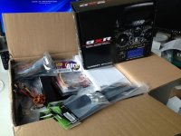
two big boxes from hobbyking. european uk warehouse shipping was within 5 days. the boxes included

.) afro 30a esc simonk
.) 9xr remote
.) 8 channel receiver
.) 1500mah life receiver battery
.) multiwii pro with gps
.) 10" propellers
.) 1100kv d3530 motors
.) turnigy nanotech 3s 2650 25c battery

i already started connecting the multiwii and a bt serial board to do remote config from my android phone. i also ordered a bt4.0 board to use multiwii gui for ios on my iphone. it works fine now and shows all value on the phone or pc and you can configure it.
i also ordered microswitches to replace the wobbly rubber switches in the remote and get some tactile feedback when pressing the buttons.

i'm still waiting for the frame and oled display as those come from china warehouse. so it may be 2-3 more weeks waiting until i can start building.

IMG_0066.JPG
IMG_0067.JPG
 
Nice man!

But you might want to get some bigger batteries eventually, I have been using 8000mah 3s, 30c, works really well...

So now, what you can do

-Get out flight controller,
-Install Arduino-
-Open up arduino, Plug in Multiwii pro board,
-make sure windows has installed the board, check device manager
-Select Arduino Mega 2560- under tools tab i think in arduino
-Download multiwii firmware - https://code.google.com/p/multiwii/downloads/list
-Clear EEPROM, wait for it to upload.. ( check youtube) via arduino program, Clear eeprom is a example sketch
-Power cycle board.
-Open up the Multiwii firmware, You should see multiple tabs in arduino, select config.h
Run through all the Code, define what you need

Your board is this one #define FFIMUv2 Multiwii pro red from hobbyking, gps inc
GPS is on serial port 2, and the baud rate is 57600 ( check in code to set serial 0 1 3 to 115200 baud rate and 2 as 57600)


And your gps is configured like this in the config.h, if it does not work, switch RX and TX running from gps to FC..
/**************************************************************************************/
/*********************** GPS **************************/
/**************************************************************************************/

//#define GPS_SIMULATOR

/* GPS using a SERIAL port
if enabled, define here the Arduino Serial port number and the UART speed
note: only the RX PIN is used in case of NMEA mode, the GPS is not configured by multiwii
in NMEA mode the GPS must be configured to output GGA and RMC NMEA sentences (which is generally the default conf for most GPS devices)
at least 5Hz update rate. uncomment the first line to select the GPS serial port of the arduino */

#define GPS_SERIAL 2 // should be 2 for flyduino v2. It's the serial port number on arduino MEGA
//#define GPS_PROMINI_SERIAL // Will Autosense if GPS is connected when ardu boots.

// avoid using 115200 baud because with 16MHz arduino the 115200 baudrate have more than 2% speed error (57600 have 0.8% error)
#define GPS_BAUD 57600

/* GPS protocol
NMEA - Standard NMEA protocol GGA, GSA and RMC sentences are needed
UBLOX - U-Blox binary protocol, use the ublox config file (u-blox-config.ublox.txt) from the source tree
MTK_BINARY16 and MTK_BINARY19 - MTK3329 chipset based GPS with DIYDrones binary firmware (v1.6 or v1.9)
With UBLOX and MTK_BINARY you don't have to use GPS_FILTERING in multiwii code !!! */


#define NMEA
//#define UBLOX
//#define MTK_BINARY16
//#define MTK_BINARY19
#define INIT_MTK_GPS // initialize MTK GPS for using selected speed, 5Hz update rate and GGA & RMC sentence or binary settings
 
Multiwii PID tuning for baro ( print this)


------------------------
"PID settings for ALT works like this:

*P - means how much copter should relay on the baro sensor. Higher the value is, stronger the copter relays on the Baro reading. ( check the readings live to give you an idea on how accurate it is...)
*I - is used to compensate drift costed by battery voltage drop during the time. Higher the value is faster the copter will react to voltage drop ( or other factors ).
*D - means how strong the copter should react on data from the accelerator. It is used to react on small up and down movements. Higher the value is copter will react faster/stronger to the small altitude change.

Tuning:

We need to start from settings the Accelerometer.

1. So set the P and I to 0

2. Start to play with D value only. To high D may cause yoyo effect (up and down oscillations). With to low D copter will be not able to react strong/fast enough to hold altitude. Your goal here is to set D to the value when copter don't oscillate up and down and also holds altitude quite well for a not very long period of time. Copter will not hold altitude perfectly at this point during long periods. It will slowly drift up or down, but altitude should be quite stable in short periods.

3. Start to increase P to the point where copter holds altitude over long time period. If the value is to small the copter will drift slowly up and down. If the value is to high yoyo effect may appear. Goal here is to set it to the point where copter holds altitude for quite some time. Copter will still go slowly down due to battery voltage drop over time.

4. "I" is used to compensate the voltage drop. So start to increase the "I" value slowly until you get a perfect position hold during a very long time
 
My PIDS for ALT ( altitude hold)

P: 1.5
I: 0.065
D: 30


I used foam over the barometer sensor with a zip tie..
But I found even better results using a tubberware or plastic container, Making sure all vent holes have foam, and you can experiment on windy days having foam over the sensor or not when using the container. But I have had some really solid performance like 40cm dift at the most which is pretty good.
 
Got my Hubsan


Been through two charges...nothing broken so far. In a word i "suck" at flying :mrgreen: , throttle is quite sensitive so might try knocking that down and might have a go at expert mode. no flips yet
 
one important thing that i forgot to order are WIRES. wires from receiver to multiwii. and you need a lot of them. if you want to control all ports (aux1,2..) you need 8 female/female plugs. even though they are often named male/male, but the plug inside is female. the male pin is on the board and receiver.
a bit of confusion is the type of plug as well: there are futaba and graupner/jr types. both are pin compatible (more or less) but use different colors for the wire, and normally are in-reversible. each of them does it in a different way, and receivers etc are mostly made to accept both types. for the controller board it doesn't matter as it has no reverse safety connection feature anyway (all pins are uncovered).

258000012.gif
 
Back
Top