Re-wind of a turnigy 80/100 (Now-tutorial w/Video)

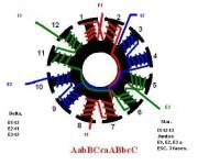
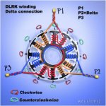
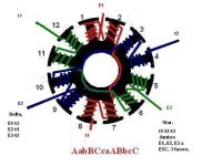
DLRK is the pattern I use most often for maximum copper fill. Delta & Wye.
I often use some 5-minute JB-Weld epoxy to hold windings stable from vibration.
I use a slower drying higher-temp JB-Weld to glue hall's into a stator.

Etard won a heat race running a 6-turn DLRK/WYE terminated motor on 18S. We re-geared his bike for a little more top speed before the event...but he is running a 12-FET xie-chang at 5-Kw peak battery draw as measured on the CA. (from last october IIRC)

I smoked 2-LRK wound motors at the Bairdco Race a week ago...over geared & only running a single motor set up....didn't help it was 107F when we arrived at the track that afternoon.
 
Hey Thud,

Sorry to ask again but just wondering if you got an idea of the kV of your LRK wind? I would like to rewind my motor that way but i cant change my gearing much. Just after a ball park figure... Thanks,

D
 
I wound the LRK's to match the stock wind.
8 turns dlrk is = 2 a 16-turn LRK wind...(exact same copper fill...maybe a % point less when end turns are calculated)

Spinning up on a castle HV-160 yielded 7500-ish rpms on the 80-85's using a weak 12-cell pack...a perfect 170-Kv.
 
Thanks for that Thud, appreciate it.

I need around 100kV so from my very basic understanding of motor winding i need to wire around 9-10 Turn... I think, will read up.

thanks again,

D
 
I have never used that idea with the JB weld but have seen it many a time.

I use LRK in my 100mph+ park flyer, so a much smaller scale and had to do lots of rewind because of wire vibration. I found a new link on high quality enamel wire, slot insulation and the "Dolph's" spray though at a local shop; it helps a lot and all rated at over 200C. I ve done some rewinds of the hobby motors, a small geared hub and trying a 9C hub unsuccessfully(Im thinking the copper is too large of diameter to fit between stator slots)

I am looking to move up to BLDC for my electric skateboard and am trying to decide on a motor, not necessarily a rewind; I hate rewinds!!

I also noticed your molds Thud, it seems like you could benefit from one of the 3D printers I sell. They have excellent tolerance ...:D
 
Jeremy Harris said:
Excellent job, Goethe, and really good results. This has really given me encouragement to do something similar when my motors arrive. The low no-load current is pretty good, too, as it's a good indicator of a reasonably efficient wind.

Where did you fit the Halls? Are they inside the motor, between the slots, or outside the motor on a bracket?

I have some thin, tough, Kapton tape that I might use to help insulate the stator from the windings. The last motor I wound with thick wire was a smaller, 50mm diameter stator and I found that winding 1.2mm wire was tough; 1.6mm must be a real bitch to wind tightly, my hat goes off to you!

I've been seriously looking at using some rectangular wire for this next wind. Although it's a bit more expensive I think it might be easy to wind than round for thick gauge stuff, plus I'd get a better fill ratio. Has anyone else tried this?

Jeremy
I am only up to here in this thread. My question may be answered later in the thread but being and motor rewinder years ago. i have to ask why are you using such thick wire and not two or three smaller wires to give the same cross sectional area? Easier to work with and better fill. It doesnt look as pretty but should still work.
 
winchmeup said:
I am only up to here in this thread. My question may be answered later in the thread but being and motor rewinder years ago. i have to ask why are you using such thick wire and not two or three smaller wires to give the same cross sectional area? Easier to work with and better fill. It doesnt look as pretty but should still work.

The copper fill usually ends up worse with lots of thin wires, because of all the extra insulation and also because it's very much harder to get lots of thin wires to lie neatly in rows, as they tend to want to cross each other and twist, wasting space. In practice thick wires wound neatly tend to give a better true fill factor, as far as I can tell based on only a limited number of motor winds.
 
thanks for explaining. finally finished reading all this post. nearly lost me when it started onto the cooling debate.
Cant wait to see what Thud gets fromthe latest wind.
So have we an answer on the best controller for a modest rewind. Something in the middle of standard wind and a mild rewind?
 
I read this topic with much interest. i recently rewind a C80100 130kv motor to be used as a direct drive outboard motor.

My goal was to rewind this motor to 60kv and aiming for a low copper loss.

I managed to rewind the C80100 with 4x1mm (18AWG) strands in a 10 turn WYE DRLK configuration, which is about the maximum fill.

The motor runs perfect and smooth and the Rwye is measured at 28mohm (56mohm per phase).

I hope someone can help me to understand why the measured KV rating is different then i calculated. I measure an
no load RPM at 39V of 3120RPM: 80kv

I calculated and checked the kv rating with the table on the first page of this topic
130kv / sqrt(3) = 75kv (wye iso delta)
75kv x (8 original turns / 10 rewind turns) = 60kv

Does the DRLK winding scheme make the difference or is my measurement method incorrect, i hope someone can spot the error.

btw: I use an RC ESC to control the motor and i have several brands in use and i notice that the hobbywing SEAKING 130A HV is absolutely brilliant. The rewind motor locks up using an Aoelian XP120A HV controller and the Himodel ICE 120A HV controller blows up the first MOSFET, so that seems to be bad design of the ESC
 
Hello everybody, i need a little help on choosing how to wind my 80_100 motor, i have read this thread and many other threads on rewinding + youtube, but i can't seem to decide on what winding scheme to chose....

My needs are a motor with a KV of 76 (8 turns WYE) but what to do winding wise...

Do i wind it in:
ABCABCABCABC - LRK
AabBCcaABbcc - DLRK
ABCABC - LRK (every second tooth)

I got the motor stripped and got more then enough 1.9mm / AWG 13# wire.
Just need help on what wind would be best, the motor by "default" is going to be run at 25V (8S LiFe) and im hoping for a RPM of 1900.

Oh and this is for my 2 E-Moped, a converted Suzuki K50 im beginning on next month (time is short right now...)
20121010_001.jpg


----------------------------------------

And if anybody is interested in 1 E-Moped it is my Electro Ciao :)
This has been my primary transport for the last 2.5Years, clocking over 8000Km so far.
ciao004.png

Info:
Motor: C6374-200kv (the old blue one)
Controller: Hobbyking SS Series 90-100A ESC (Which is a lie... it actually pulls 125A..)
Battery: Headway 16AH cells arranged in 8S2P for 25V 32AH, Range 30KM+ (Longest travel so far just over 31KM)
Drivetrain is stock, had an axle made for the motor that starts at 10mm as the motor is and goes out in 12mm and then into the stock clutch that the Vespa Ciao uses.
Oh and Top speed is 30'ish Km/h, Danish law on mopeds says speed SHALL be 30Km/t and "bigger" class of 45Km/t.
But it makes up for the low speed by accelerating HARD :)
 
Hello dr frost,

I will recomend the dlrk winding pattern AabBCcaABbcC

the ABCABCABCABC pattern will not work well (or at all) with 14 magnets in your can.

also the LRK A-b-C-a-B-c will work well with 16 turns on each tooth that is wound terminated in wye.
the space is a skipped tooth on the 12t statror

hope that helps
Good Luck & have fun.
 
Thanks, only one more thing, i been searching like crazy about winding diagrams and the dLRK comes up in various diagrams.

Is this the one to go by?
I just want to be sure and get the best result and the desired 76'ish KV.
 

Attachments

  • 12N-14P-DLRK.jpg
    12N-14P-DLRK.jpg
    30.6 KB · Views: 6,500
yes that one is a good example.
pay attention to the "starts" on the 3 phases. You'll want to keep the juice flowing in the same directions.

To make room for the terminations on the smaller motors, I'll add a 1/2 turn & terminate on the back side of the stator...I also recomend you write the winding diagram directly onto the stator, for a quick visual reference...it will save you time in the long run.

its amazingly easy to lose your place (don't ask me how I know :oops: )
 
Thud said:
its amazingly easy to loose your place(don't ask me how i know :oops: )

+1 +1 +1 Be the best move you could make....likewise, don't ask me how i know LOL
Thud told me to do this initially i thought meh ::shrugs:: doesn't seem thaaaat
important.., i can do without 8) boy was i wrong... :oops:

KiM
 
file.php


I just rewind my C80100 using this diagram in wye star configuration, where t1,t2,t3 are connected together and E1-3 are connected to the controller.

After the rewinding i measured a wrong KV rating, using an open-load/max rpm method, I posted this in a previous message http://www.endless-sphere.com/forums/viewtopic.php?f=30&t=20618&start=270#p648455

I started to investigate why the KV rating is off, and i found out that i think that the diagram is wrong !!!

The diagram does not correspond with the winding scheme as mentioned below the picture below the diagram.

I found out that there is an error in the diagram when i measured the KV of each phase-phase connection separate. The voltage between E2-E3 and E2-E1 are the same and the voltage between E1-E3 is almost 50% lower!

This means that there is an winding error on phase E2/t2 and checking the winding directions on the diagram with the AabBCcaABbcC DRLK scheme I noticed that indeed E2-t2 is running the wrong way around the poles. The diagram can be easily fixed by renaming E2 into t2 and vice versa.

So i really wonder if somebody else rewind a motor using the diagram literally and if somebody can confirm my finding! I noitce that this diagram is used often and i hope that someone can check my findings
 
SAM_0423.JPG


This motor is rewinded with 4x1.0mm (18AWG) 10 turns in WYE DRLK configuration

SAM_0343.JPG


I wrote a rewinding protocol to rewind the motor step by step and checkmark each turn, as it really easy to make an error, i have to correct
this protocol if my findings in the previous topic are correct, so i can share this later
 
Well when i keep looking at that diagram something really seems off, i don't think it is the reversal of E2 and t2, more that the E2 just seems off, if i look at E1 and E3 and compare with E2, E2 just does not seem right, can anybody confirm that the diagram is right or wrong, there is still atleast 1 week before i begin to rewind my motor so i would like to be sure.


EDIT:
Also found this diagram, which i would change to WYE, but is it any good?
It seems to be: AaBbCcAaBbCc
 

Attachments

  • dlrk-winding-diasmal.jpg
    dlrk-winding-diasmal.jpg
    79.3 KB · Views: 6,423
I just have altered my rewind C80100 used t1, t3, E2 as starpoint, and E1, E3, t2 as the motor connection.

And the motor is working perfect, i measured a KV of 62 and a no-load current of 3A (with the load of a gear reduction and propellor in air)

To me the diagram is definitely wrong!

The motor will run and perform if you rewind as per diagram but will perform poorly, as one phase is working the opposite. I noticed this
by measuring a wrong KV and high no load current of about 16A when running at max speed. The magnetic field will be weakended by
the phase in the wrong polarity and therefore the motor will run faster and will not perform.

I wonder who used this diagram as well and what the findings are.

To correct the diagram you either:
- swap the t2 and E2 text in the diagram, so use E2 in the WYE startpoint, or:
- rewind the coils around teeth 3,4 and 9,10 in different direction

I only understand a drawing for rewinding. Using CW or CCW makes me confuse as to me it is not clear as from which point of view to use the stated direction. I write on each teeth the origin teeth of the winding and the direction.
 
I just did a quick redraw of the rewind scheme, doesn’t this seem more like it should?, it fits with the AabB.....

And now is should just be wired up as "normal", E1,E2,E3 to ESC and t1,t2,t3 together for WYE connection
 

Attachments

  • 12N-14P-DLRK (copy).jpg
    12N-14P-DLRK (copy).jpg
    30.3 KB · Views: 6,416
drlk_wye_12p_sml.jpg


This is what the drawing should look like in my opinion, please help me to check and confirm
 
tdejong said:
dr_frost_dk: i agree with your corrected drawing !

Thanks, yours is almoust there, maybe you can re-edit it like the one i just did, it is just phase 3 (blue) that is a bit off, it would be nice to have this wiring diagram that looks as good as the one you posted :), the re-edit i did works but yours is much easier to follow.

EDIT: didn't notice that you did the winds from out to in (on the stator), so i think yours look corrected anyway as it is.... sorry for the confusion.
 
drlk_wye_12p_altn_sml.jpg


This is the same wiring diagram as the one posted by dr_frost_dk, and is an alternative to the one i previously posted. Both diagrams will work !

I think i like this one better, because the wires connecting the opposite pole-pairs are nicely distributed around the stator
 
Back
Top