Simulation is significantly different than actual results

I don't think increasing current ever reduces the heat in the motor due to I squared R. It may allow the system to crest the hill sooner and reduce the integrated heat-time total however.

Slope and system mass in our experiment here are taken as constant, battery voltage is high enough to allow the constant current we choose. More on that now:

I squared R in the motor produces two things. One is heat. The other is the magnetic field that makes torque.

If we hold current constant then the heat is constant (ignoring the much smaller heat from hysteresis losses, etc that will grow at high speeds).

If the RPM is zero the back EMF is zero and the voltage required to maintain our value of constant current is low. All the power is all going into heat.

As the motor accelerates the back EMF rises, and the voltage required to maintain our value of constant current increases. The I squared R heat is not changing (ignoring the small change due to R increasing at the motor heats). The increasing voltage needed to maintain the current is contributing to useful work. The additional power from the current times the increased voltage is doing useful motor work climbing the grade.

The controller generates a voltage step-down from the battery to the motor with PWM. It can maintain a constant current up to a point where the PWM reaches 100%, then the current will fall off with increasing RPM. To maintain the constant current (and torque) at higher speed would require raising the battery voltage, or lowering system resistance (better wiring, lower IR batteries, lower IR controller, lower IR motor) or less back EMF (different motor or winding).

Another technique for increasing speed beyond 100% PWM and the battery voltage limit is to employ "field weakening" and use some current to generate a magnetic field that effectively opposes and weakens the permanent magnet field at the rotor which changes the torque and speed constants of the motor and makes a motor with less back EMF so more speed is possible. This is similar to changing the timing of the rotating field vs the rotor.
 
As I see it, in certain circumstances increasing the current allows the motor to operate at a, greater, more efficient speed. More heat is inevitable (I^2R) but more work is also done (= hill climbing). Faster speed also means greater heat dissipation and sometimes these two factors outweigh the increased I^2R heat and you get further up that hill for a given rise in motor temperature.

At some point of increasing current and speed, you may be achieving higher efficiency and work done, but an increasing proportion of this will be used to overcome air resistance rather than achieving your objective of hill climbing. At that point you will start over-heating the motor lower down the hill.
 
Punx0r said:
As I see it, in certain circumstances increasing the current allows the motor to operate at a, greater, more efficient speed. More heat is inevitable (I^2R) but more work is also done (= hill climbing). Faster speed also means greater heat dissipation and sometimes these two factors outweigh the increased I^2R heat and you get further up that hill for a given rise in motor temperature.

At some point of increasing current and speed, you may be achieving higher efficiency and work done, but an increasing proportion of this will be used to overcome air resistance rather than achieving your objective of hill climbing. At that point you will start over-heating the motor lower down the hill.

Well said.
 
dogman dan said:
I still smell a rat, that you actually slowed to 3 mph.
Correct! There was a rat lurking. Humm...I'm looking for just the right smiley for this situation... Nope, can't find it. Must go to Youtube for this one
https://www.youtube.com/watch?v=lBEn3a4TIUw
Dogman dan is the man!

Hang around and I will tell you a tail... A rat tail.

The build
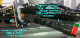
When I built this bike my controller came from Grin Tech and the battery I ordered from EM3ev. I needed to change the power harness on the controller to mate it.

20140909 Power Poll mod.jpg

The burn
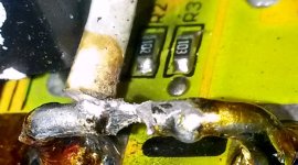
This worked great but for one mistake. When I re-assembled the controller, the insulated wire from the switch was laying across the shunt. Not a problem until I was climbing some steep hills in Utah and the shunt got hot and melted the insulation. The shunt is at battery ground and the switch wires are at battery voltage (~52V). No one had a chance once the insulation was melted.

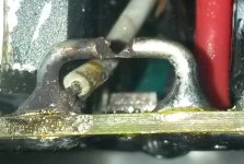
A crater was blown in the shunt.
20140908 Blown shunt.jpg

And the switch wires evaporated.
20140909 Wires eveporated.jpg

The fix
Being on vacation, wanting to get the bike back on line and unsure where to find a suitable shunt in Southern Utah I did what any hack would do that packs a soldering iron on vacation. I bridged the shunt chasm with solder of course.

I realized that this was only good for a temporary fix but I am too familiar that what is temporary at the time will hang around much longer than it should. I should know better. But, Hay! My bike was was back on the road! I re-calibrated for the modified shunt. It was 3.050mOhm out of the box. Modified, it became 3.005mOhm. Not Bad! Life is swell.

I came home from vacation. I still could not figure out where to find a shunt. I think figured that it must have been made of manganin so I was searching for manganin wire. No successes searching that way so I forgot about it.

In February, weather started getting better in the SF Bay area; I recognized an opportunity to participate/support local Boy scouts on a Livermore to Yosemite trek, 175 miles in 3 days. So I started training for it. I would be the only ebike on the trip. On the training rides I challenged myself to get my electric energy use below 6Wh/Mile for 50+ miles to prepare for the trip.

I completed the Yosemite trip in April 2015. The bike worked fine as far as the electric drive train is concerned. No big stress on electronics when I am going 100 miles (first day) on 615 watt-hours!

The experiment
On the Yosemite trip, and on other occasions, I have been asked lots of questions about the performance of this bike. That motivated me to perform the experiments described on the original post.

The commute
When I started shopping for parts to build this bike, my design criteria was that I wanted something that I could use to ride to work. This means 25 miles one way, with a ride on BART (electric train) in the middle of the trip. I finally did it last week (on June 22nd, 2015).

The rat detected
On my commute home I started with a full charge. When I got home I looked at the readings on the CA. Battery voltage 50.9V (14S Li-ion NMC). Capacity used 11.28Ah (out of 12.3Ah). That's when I thought of dogman dan's prophetic words and remembered my solder shunt because those two numbers just did not seem right. The best I can tell, 50.9V indicates about 75% battery spent and the 11.28Ah indicates 92% usage. An uncalibrated shunt would cause that difference! So I did a calibration procedure. It was 3.005mOhm when I repaired it last September. It now came to 4.107mOhm! That would more than account for the difference in the capacity calculations. (The voltage method is ball park.) I knew I had to try harder to find a replacement shunt. The google search that turned up the clues that I needed was "endless sphere manganin". I went a head and ordered the part on a Wednesday. I did not want to open my controller until the part arrived. I figured the 5 watt 3mOhm part would be the right choice: P=(I^2)*R, solve for current (I) we get 40A. Should work for a 25A controller.

The extermination
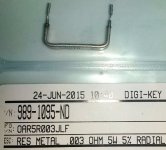
It only took two days for my shunt to arrive even though I chose the slowest shipping option. I could not see paying more than $3 shipping on a $0.75 part. Just in time to start Saturday morning!

20150626 New Shunt.jpg

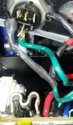
Time to open the controller.

20150626 Melted solder shunt.jpg

Yep. That looks like a melted solder shunt...

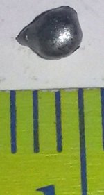
And, ho ho, what's this that fell out of the controller?

20150626 Bad solder blob.jpg

A blob of solder, 2mm. That looks like it would be the right size to have dripped out of the solder shunt. I know what you are saying right now. Yes, I am fortunate that did not short on something.

Hmm...the shunt foot print is quite a bit smaller than the one I ordered. Well, only one thing to do. It's a Saturday. I can't wait until Tuesday for another shunt can I? Besides, it's a 40A shunt. Got to keep it!

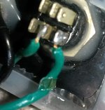
20150627 Finished job.jpg

Oh, still too high. It will hit the switch leads when I close the controller. This is a DPDT switch and it only needs a SPST. So I moved the green wires from the polls that would hit the shunt to the unused set and cut off the switch polls that are not needed.

Closed up the controller. Re-calibrated the shunt, 3.195mOhm. Not bad.

The conclusion
It is quite possible the solder shunt melted while running my hill experiments and would account for the poor performance for two reasons. As the shunt shed mass the resistance would increase. Also, solder does not make a good shunt since it's resistance nearly doubles with a 100C increase in temperature according to a chart that I found.

If the CA is set to limit current to 25A and "thinks" the shunt is 3.005mOhm when it is actually 4.107mOhm then the actual current limit is 18A. Perhaps, when hot, the solder shunt is as high as 5mOhm yielding a 15A current limit, exacerbating the problems discussed in this thread.

Forward
When I get some time, I hope to run some more hill tests and see the improved performance while looking for warm connectors as dogman dan suggested. I will return when I get new results.

Yes, this shows that my test results in the OP as a comparison to the simulation is invalid but this thread has produced some good, educational, technical discussion!

Thanks y'all!
 
Nice rat catching! Well done.

Climbing that hill with more than a 10 amps controller should go faster, and get closer to the sims predictions for sure. You were just stalling the shit out of that motor without enough watts on that hill.

FWIW, none of the other posts in this thread are wrong. As you stall out a motor, it does go into this death spiral of inefficiency that often ends with melted halls at least, if not complete combustion of a motor.

But the rat I smelled, was you should never have been stalling quite that bad in the first place, given the wattage you thought you had. I was thinking along the lines of 2 phases running at 1000w, the third running at 100w or something like that.

Planes crash for similar reasons, something messes up an instrument, and the pilot crashes thinking the instrument was correct. In your case, your CA was way off, because it's tied to that shunt that was no longer the same. But I felt sure that somehow, you were not running right, and the wattage display you saw was not going to the motor. Sure enough, you had a lot less power to the wheel than the CA showed.
 
dogman dan said:
...none of the other posts in this thread are wrong.
Agreed. And they have all been very informative.

dogman dan said:
Sure enough, you had a lot less power to the wheel than the CA showed.
Agreed, and not only what the CA showed but, for those folowing along at home, the CA was limiting the current at somthing significantly lower than 25A.
 
Make More Pi said:
...and not only what the CA showed but, for those folowing along at home, the CA was limiting the current at somthing significantly lower than 25A.
Yes - due to the damaged controller shunt.

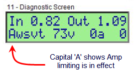
Unfortunately, the 'limit flags' shown on the V3 diagnostic screen are not part of the V2 product. With a V3 the CA 'Amps' limit would have been readily apparent and a hint that something was awry with the Shunt calibration...

V3AmpLimiting.png
 
teklektik said:
With a V3 the CA 'Amps' limit would have been readily apparent and a hint that something was awry with the Shunt calibration...
Yes, the "A" limit flag shows that the CAV3 is limiting the current during the climb. The CA "thinks" the current limit is set to 25A but
teklektik said:
due to the damaged controller shunt.
the actual current limit could be more on the order of 15A.

Being a novice, not accustom to how my bike ought to perform under the conditions described in the OP; it took riding at a different extreme, one that I am much more accustom to (25 mile commute, ~15Wh/mile), in order for me to detect the problem. By experimenting in what was for me, a new extreme (>1 mile, >6% up hill, full throttle, no peddling), I learned how my bike performs (or doesn't) under those conditions. The blogging about it has taught me much more.

No, for me, the fact that I was hitting the current limit was not a hint of anything since it was pretty much what I expected. At full throttle I expect to either hit my current limit or my speed limit. I certainly was not hitting the latter. Hitting the former at 3mph was a surprise for me and the purpose of blogging was to learn what it meant. I was resigned to the idea that is just the way it is. Not a stellar hill climber. This may come to a surprise to everyone but I have never ridden an ebike that is more powerful than mine, as mediocre as it is. So I have nothing to compare it to but lower power ebikes. And, I never saw an actual ebike (except for on youtube) until I built my wife's Bionx.

I am now excited by the prospect that the next time I get a chance to do some HP hill climbing I will see better results!

I am grateful to have ES to help lift me out of my naivete. :)
 
One thing I've learned in building a few ebikes is that doubling the torque makes a HUGE difference. You'd expect improvement, but the difference is staggering. I'm about to try that experiment again by putting a front motor on a 9C DD rear motored mountain bike. Based on what others have reported, I expect a similar transformation - from an "okay" hill climber to a "rocket". From a nearly melting motor to a pair of hardly working motors for the same gradient.

Going from 15A to 25A is not quite a doubling, but it gives you a flavor of what doubling would do.

Enjoy your repaired ebike, and hope to see you around.
 
Two motors definitely makes a good climber. Even if the second motor is not so strong, 1500w will climb nice. 2000w climbs great, whether its one big motor or two medium size motors.

I was going to put dual motors on my cross country cargo bike, but then when I got a 5204 clyte, it was just easy to run it on 2000w and climb huge mountains packing heavy loads.
 
Cromotor for the win of course.

But a regular HS crystalyte, or Muxus 3000w will easily handle 2000w, which is enough for climbing most long paved hills, even with a total weight of 400 pounds.

Of course, 10,000w to a cromotor will climb it better, but maybe you don't want to blow that much power, if the other side of the mountain is 50 miles to the next plug.
 
Now that my controller is repaired, I am back with new test results.

Independence day morning, I went back to my test hill with the thought of running two experiments so that we can see the difference between a cool-ish and a warm motor as well as to compare more accurately with the Grin Tech simulation (now that my CA can now read a shunt that will not wildly change resistance or go out of calibration).

So that I can start with a fairly cool motor, I was able to drive the bike in the SUV to the top of the hill and find toll free parking there. This means descending the hill before I can begin my test. As far as I can tell, the ambient temperature was about 18C. Rather than using regen breaking which would heat the motor I kept it slow and used friction breaks only. Nevertheless, the motor still gained some heat just by the magnets spinning past the coils.

At the start of the first run the motor temperature was 28.0C and the battery voltage was 54.6V. The hill is 1.4 miles with mostly 8% grade but for one bit that is 9%, 1 mile into the run. I go full throttle (25A, no pedaling) to where the road plateaus. The grade is 1% up hill where I stop. The 9% bit is the point that I had slowed to about 3 mph when I first did this test a couple months ago (see OP for conditions).

When I reached the top, the motor temperature was 79.4C, battery voltage was 51.6V. My average speed was 15.3 mph and the minimum speed was about 14 mph at the 9% bit. I call that a win for the Grin Tech simulation! It predicts 14.3 mph for Clyte H3540, Battery 51.8V 0.08ohm 12.3Ah, 25A IRFB4110 Controller, full throttle, 26” wheel, mountain bike, 250lbs, 9% grade.

The sim also predicts that I would overheat (150C) in 16 minutes. According to justin_le it should actually overheat sooner. I agree. This run took 5:28 and we saw a rise of 51.4C. I am not going to test that theory.

justin_le said:
The simulator is not modeling the phase current limit of the motor controller as well as the effects of higher temperature on the motor winding resistance, nor saturation effects either, and so you need to be mindful of this especially in the region where the motor is in the current limited region and especially at low speeds near a stall.
Even though, the sim does quite well!

Now for test #2. This time I want a warm motor. 79.4C at the top, that's a good starting point. This time, with regen braking, I kept the motor quite warm on the descent. A little too warm at the bottom so I waited for it to cool some before hitting the hill again.

At the start of the second run the motor temperature was 43.7C and the battery voltage was 52.5V. Ambient temperature is now about 19C.

Riding up the hill this time, I had an eye more closely on my temperature and speed. If we only see the same rise in temperature then we should see 95.1C at the top.

When I hit the 9% bit my speed was 12.3mph and temp was 89.9C. That's squeaking by! As I neared that point I was hoping that my current rollback, programed in the CA at 90C, would not effect the test until I passed that point. Just as my speed began to increase due to a slightly more shallow grade, the temp rolled over to 90.0C. My speed continued to increase, nevertheless.

I finished the run in 5:50 with a motor temperature of 95.0C, battery voltage of 50.4V. My average speed was 14.4 mph and the minimum speed was about 12.3 mph at the 9% bit. Yet more proof that hotter motors are less efficient.

Wow, nearly the same rise in temperature each time! Perhaps we have two opposing effects at play? A hotter motor is less efficient and should increase the rate of temperature rise. On the other hand, we had current roll back at the end; gradually tapering from 25A to 21.8A for the last 0.4 miles. Less power to heat the motor but also slows the motor which makes it less efficient and would make it hotter. It appears that these affects balanced out this time.

I'll end this with a few more pieces of data.

Test #1 109.9Wh, 79.5Wh/mile
Test #2 112.6Wh, 81.5Wh/mile

Yours in science and engineering...
 
Back
Top