• Hello ES! We could use some help to get us past the finish line on building the new knowledgebase for the forum.
    Can you donate? Please see our fundraising page. Thank you!

Spot weld thermocouple to 18650 cell

Zambam

Power poster
Joined
Dec 17, 2021
Messages
1,650
Location
NYC
I recall seeing videos from @ZEUS-FL using Kapton tape to fasten a thermocouple probe to a battery to measure cell temp under high current discharge. The probe would fall off when the cell gets hot.

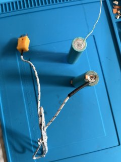
I just got a AwithZ UF20B spot welder and been doing a lot of practice welds with it. One was welding thermocouple wires to make a wire "bead" and also weld the thermocouple wires to the + and - terminal and also to the cell body. This should make much better thermo contact and will not fall off.

Edit: In the video, there are 2 thermocouples. One is welded to the negative terminal (with no connector), the other welded to the body, with a connector plugged into the meter. As can be seen, the response is immediate.


IMG_1170.jpeg


IMG_1173.jpeg


IMG_1174.jpeg
 
Last edited:
To make a wire bead, strip the wires, twist together, place on top of copper strip. There's a small square of 304 stainless at the end of the copper strip to add resistance. One welding probe presses the thermocouple wire onto the copper strip, the other probe onto the stainless. The current flow is through the thermocouple wire, through the copper strip, through the stainless. Thermocouple wires do not stick to the copper. That's a piece of soapstone. Anything non conductive should do.

I used gear 1, lowest on my AWithZ UF20B. Depending on how powerful your welder is, you may have to experiment with using longer stainless strip to control (lower) the power.

Edit: My welder probes has rounded tips. It helps to use pliers to flatten the twisted thermocouple wires first before welding so the probe is pressing against a flat instead of a round surface.

IMG_1177.jpeg
E
 
Last edited:
To spot weld thermocouple to the negative terminal, place twisted thermocouple wires on negative terminal, small strip of copper and 304 stainless held on with magnet. One welding probe press the thermocouple wire onto the negative terminal, the other probe onto the stainless. To weld onto the side body of cell, scrape a spot with razor, one probe press the thermocouple wires onto the body, the other probe on the stainless/ copper sandwich held onto the negative terminal (never on the positive terminal! will probabably start a fire or explosion)

This procedure works for me. Experiment, you may find a better way. If you do, please share.

IMG_1178.jpeg
 
This is the kind of clever thinking I like to see here, I don't know that I would use it for batteries as thermistors are a more common and better choice and epoxying those on works just fine for the timescale involved but this method could be super useful for putting a thermocouple on something that is very hot as other methods would fail at those temps.
 
This procedure works for me. Experiment, you may find a better way. If you do, please share.
Interesting! Thank you for posting that.
How does the temp reading compare between welded and taped?

I’ve never had problems with using Kapton or polyester tape holding a thermocouple onto at least a couple thousand of cells at up 120°C. Even after being reused several times. But I can see some real benefits to welding the bead to a cell for things like cycle life and other long term testing.

The image below shows 2.5mil (thickness) polyester tape. The end of the strip looks like it is peeling up because I fold both ends over a bit to create non-adhesive “pull tabs” so it’s easy to remove the strip and re-use it.
 

Attachments

  • IMG_4290.jpeg
    IMG_4290.jpeg
    868.9 KB · Views: 9
Last edited:
This is the kind of clever thinking I like to see here, I don't know that I would use it for batteries as thermistors are a more common and better choice and epoxying those on works just fine for the timescale involved but this method could be super useful for putting a thermocouple on something that is very hot as other methods would fail at those temps.
Thermistors are definitely a lot more common, much less expensive, and are much easier to use but thermocouples are a much better way to measure cell temp IMO.

Thermistors are incredibly slow, with time constants around 20 seconds for the common bead thermistors. This means the readings will always be lagging and low at high current levels. There is also very poor thermal coupling between thermistor beads and the flat or convex surfaces of a cell. This results in lower readings too unless the bead is epoxied (as you mentioned) on or a dab of thermal paste is used (with tape).

There are “fast” flat thermistors but their response time is still about five seconds.

Thermistors can also be a lot less accurate than thermocouples, often several degrees-C off. I did several tests a year ago and many were 4°C-9°C off.

The type-k thermocouples I use are calibrated and spec’d at +/-1°C accuracy with very quick response times. But thermocouples are expensive and can’t be used with any of the available BMS’ and a special circuit (or meter) is required. But they are the much better choice for accuracy and consistency IMO.

I guess, as always, it depends on what the data is needed for and what the priorties are (cost, accuracy, etc). 🙂
 
Last edited:
Thermistors can also be a lot less accurate than thermocouples, often several degrees-C off. I did several tests a year ago and many were 4°C-9°C off.
Indeed it all depends on the application, some thermistors can also be much more accurate than thermocouples, like platinum based PT ones with a decent 3/4-wire connection.

Totally agree though for testing cells hard you want that speed and BMS compatibility is irrelevant, for building a battery with a BMS I don't think you should be building battery that you are pushing hard enough to need a few extra seconds of temp reading reaction for the BMS to cut power. Or maybe those few seconds can be enough to stop a runaway but then wouldn't setting the limit lower be better. It seems many batteries I've taken apart do use very tiny thermistors, possibly for packaging and cost but also react faster than a big old metal cased one.
 
How does the temp reading compare between welded and taped?
I have not done a test with a taped thermocouple. Now that you mentioned it, I will do a test with 3 thermocouples. One taped to the body, one spot welded to the body, one spot welded to the negative terminal, all at the same time.

I’ve never had problems with using Kapton or polyester tape holding a thermocouple onto at least a couple thousand of cells at up 120°C
Maybe my recollection of the video is faulty. All I remember was a thermocouple falling off in the middle of a high current (high temp) discharge test, Do not remember if it was Kapton taped, rubber band or twist tie.
 
Maybe my recollection of the video is faulty. All I remember was a thermocouple falling off in the middle of a high current (high temp) discharge test, Do not remember if it was Kapton taped, rubber band or twist tie.
I remember that happening. A lot depends on how it’s actually taped on as any pull on the wires or the tape not tight against the cell can cause the thermocouple to come loose. I use a thick tape that’s a lot easier to handle without crinkling. A strip of thin Kapton is a nightmare to use, always flopping around.

But the adhesives (with genuine Kapton and the polyester tape I use) are rated for far higher temps than any of our cells will, hopefully, ever see. 🙂

I have not done a test with a taped thermocouple. Now that you mentioned it, I will do a test with 3 thermocouples. One taped to the body, one spot welded to the body, one spot welded to the negative terminal, all at the same time.
That will be great to see!
 
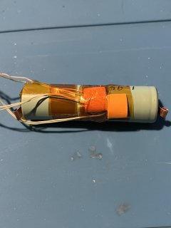
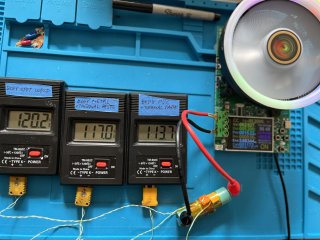
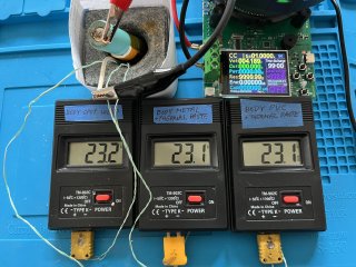
From left to right:
spot welded to negative battery terminal, taped to cell body PVC wrap, spot welded to cell body
Cell is a MX18650-26P salvaged from a bad 10S4P battery pack. I guess it's rated 2.6 Ah? Load was 5.2 A (2C) on Atorch DL24P load tester.

Highest temp was the spot welded to cell body thermocouples, then spot welded to the negative battery terminal, coolest was taped to cell body PVC wrap.

79.2F 78.6F 78.9F before test start
87.6F 85.6F 90.9F approx 4 min into test
108.5F 104.7F 113.2F approx 8 min into test
129.9F 124.3F 136.0F approx 16 min into test

Numbers are from screenshots taken from a video of the test. For some reason, I could not upload the screenshots. I get an error that they are only partially uploaded. Tried a few times - same result.

edit: I took a photo of the video on my Mac, and was able to upload the photo, which shows the test setup.

IMG_1202.jpeg
 
Last edited:
I also did a test with just 2 thermocouples, one taped to the bare can of the the body (not against the insulation), the other spot welded directly adjacent to the taped one. I feel spot welding thermocouples to the battery negative terminal is not useful since it is skewed by heat generated by resistance heating of the current flow through the battery.

From left to right: taped to metal body, spot welded to body.

Again, spot welded shows the hotter reading.

75.4F 75.2F before test start
95.0F 101.7F approx 4 min into test
108.5F 116.8F approx 8 min into test
124.3F 134.6F approx 16 min into test
 
Do you have any thermal grease?

I think a round thermocouple tip in contact with a round cell body without thermal grease under tape, has to read cooler. There is more of it in contact with the tape than the cell.

I taped thermocouples to various.parts of my engines cooling and charging system like thermostat housing, upoer radiator hose, lower hose, transmission coller input and output.
The readings were all low until I Insulated the thermocouple tip from.passing airflow with a layer of reflectix bubblewrap and zipties on both sides, and or high temp adhesive tape

The TC on my alternator stator was a fustercluck of data until I JBwelded it, AND then insulated that from airflow.

Just an FYI, the hottest alternator temps occurred at idle with a hungry healthy large lead acid bank feeding on everything the alternator could make at that low rpm with an external adjustable voltage regulator set to 14.7v.

Speeds under 25mph/40kmh were also able to cook the alternator.
68mph/110kmh and it stayed far cooler at nearly double the amperage output.

So.if you want to charge your discharged but otherwise healthy lead acid battery, drive it, don't just let it idle parked.
 
I feel spot welding thermocouples to the battery negative terminal is not useful since it is skewed by heat generated by resistance heating of the current flow through the battery.
The bottom (and top) of our round cells is also separated from the heat producing jellyroll unless it’s a full-tab cell and even then the heat flow is bottlenecked a bit.

The typical mounting point I’ve seen is halfway up the sidewall.
 
Last edited:
Do you have any thermal grease?

I think a round thermocouple tip in contact with a round cell body without thermal grease under tape, has to read cooler. There is more of it in contact with the tape than the cell.
Just found thermal grease along with other cooling mod parts I bought for my TSDZ2 mid drive I was working on a few years ago. Turns out (via tests), at the power level I run the motor at, cooling mod was not needed so none of the parts were used.

I will do another test with thermal grease.
 
This shows the spot welded thermocouple, thermal grease, the 2nd thermocouple to be taped with thermal grease below the spot welded one, and 1/16" thick adhesive insulating foam tape.
IMG_1204.jpeg


This shows three thermocouples with foam tape and Kapton tape. Two of them have thermal grease (the one against metal body and the one against PVC body). The spot welded thermocouple does not have thermal grease.
IMG_1209.jpeg

This was taken near the end of the test:
IMG_1223.jpeg

The spot welded thermocouple reads 3.2F higher than body metal thermocouple with thermal grease, 6.5F higher than body PVC thermocouple with thermal grease.

Compared to results from post#12, thermal grease lowers the difference between spot welded thermocouple and body PVC thermocouple by 3.8F (10.3-6.5)

Based on these results, when characterizing max current/ temperature of a cell, would you:
1. spot weld thermocouple to the body?
2. tape thermocouple to the metal body with thermal grease?
3. tape thermocouple to the PVC body with thermal grease?
 
Thank you for the tests and the focused photos.

I have a 4 channel Ktype display and find I can move a thermocouple from channel 1 to channel 4 and get readings of up to 3 or 4C difference, but My K type thermocouples were bought based on price.

On some of Zeus'-fl videos when he uses a thermal camera one can see the cell heat from the bottom of the can towards the cathode, but granted these are at higher discharge rates and might mean nothing on a different cell at lower rates.

But if you are inclined to test more, perhaps having all three TC's the same distance from the bottom of the cell and cell orientated vertically in an environment with no air movement, when placed under load would perhaps change the results.

I'd certainly be inclined to spot weld a TC to a cell, as thermal grease is so dang messy and contaminates everything.

I was always under the impression TC wires had to be treated delicately and not kinked, I never thought one could cut the round tip off and spot weld it.

I am not sure I understand your process for spot welding it to the can.

I do currently have a 7s2P of EVE 35V that I fear I am getting too hot starting the load at 4 amps per cell and finishing at 7, though getting through the kapton tape fishpaper and layers of heatshrink have me reluctant to get a Tcouple on it.
 
Thank you for the tests and the focused photos.
You're welcome! Want to thank you for this thread on ESK8 (I'm not a member). Learned a lot about spot welding copper from it.


I have a 4 channel Ktype display and find I can move a thermocouple from channel 1 to channel 4 and get readings of up to 3 or 4C difference, but My K type thermocouples were bought based on price.
My Type K meters are cheap in price but works good. Surprisingly, the beaded thermocouple probe that came with it was 2F off (210 or 214F, can't remember) when calibrated in boiling water, but the "bead" that I welded with my UF20B using thermocouple hookup wire was spot on at 212F.

For a long time I was using 1.5V rechargeable Lithium AAA batteries in the meter to monitor my middrive motor temp. The display would fluctuate 1 or 2 degree F up and down constantly- really annoying. For the battery cell temperature test I could not have that so I tried using Alkaline and the fluctuation stopped (edit: My guess of the fluctuation is due to the noise from the DC/DC converter in the rechargeable Lithium AAA). Since I do not have enough Alkalines (9 needed for 3 meters), I am using NIMH rechargeable which I have plenty of. The meters indicate low battery with the NIMH but do not fluctuate and seems to read the same as Alkaline.


On some of Zeus'-fl videos when he uses a thermal camera one can see the cell heat from the bottom of the can towards the cathode, but granted these are at higher discharge rates and might mean nothing on a different cell at lower rates.

But if you are inclined to test more, perhaps having all three TC's the same distance from the bottom of the cell and cell orientated vertically in an environment with no air movement, when placed under load would perhaps change the results.
I can set that up and do another test.

I am not sure I understand your process for spot welding it to the can.
I'll try to describe the process better, with photos, later.
 
Last edited:
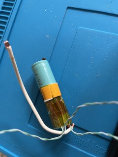
Strip insulation from the thermocouple wires, twist together, flatten with pliers a bit to allow the probe to press on it against the cell more easily instead of rolling off. The other probe is on the negative of battery. Experiment with the gear setting. I used gear 1, single pulse on UF20B. Fuses the thermocouple wires together and welds it to the cell body in one shot.


IMG_1228.jpeg
 
Last edited:
Based on these results, when characterizing max current/ temperature of a cell, would you:
1. spot weld thermocouple to the body?
2. tape thermocouple to the metal body with thermal grease?
3. tape thermocouple to the PVC body with thermal grease?
Since the cell manufacturers just tape it on that’s what I do so I can directly compare my results to theirs (helps with determining cell grade). They base their cycle life and max current specs on this method of temperature measurement so I would want to do the same.

But any method can work just fine IMO as long as it’s very consistent from cell to cell. Then each person can directly compare the cells they test, even if they can’t compare their results to anyone else’s (which is problematic anyway since so few people know how to mount a sensor well , or even care).

Thank you for the testing you’re doing! It’s great to see how and where the numbers change.
 
On some of Zeus'-fl videos when he uses a thermal camera one can see the cell heat from the bottom of the can towards the cathode, but granted these are at higher discharge rates and might mean nothing on a different cell at lower rates.
The heating pattern can also vary greatly depending on cell construction (all tab, single tab, etc.) and the cell connections (fat copper strip, tiny cell testing holder tip, etc.).

I agree that discharge rate will have a great effect on the temp-delta and the hottest part of the cell would be a lot closer in temp to the coolest part. Though some “evening out” of temp across the cell can occur for longer discharges as the cell drifts towards thermal equilibrium for the chosen current level (cell typically reaches empty before this though).
 
The spot welded thermocouple reads 3.2F higher than body metal thermocouple with thermal grease, 6.5F higher than body PVC thermocouple with thermal grease.
What variation in temp do you read if you use the same thermocouple (reading a steady “hot” cell temp) in all three of those TM-902C meters?

I’m often asked for temp meter recommendations and having a consistent, relatively accurate (consistency is much more important), and affordable model to recommend would be great.
 
What variation in temp do you read if you use the same thermocouple (reading a steady “hot” cell temp) in all three of those TM-902C meters?

I’m often asked for temp meter recommendations and having a consistent, relatively accurate (consistency is much more important), and affordable model to recommend would be great.
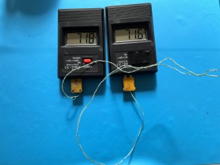
I just tried the same thermocouple in my three TM-902C meters at room temp.
1. 71.8F
2. 71.6F
3. 71.8F

Edit: It'd be difficult to get a steady "hot" temp when the cell is discharging since the temp is rising.
Screenshot 2026-02-16 at 1.51.48 PM.png
 
Last edited:
I just tried the same thermocouple in my three TM-902C meters at room temp.
1. 71.8F
2. 71.6F
3. 71.8F

Edit: It'd be difficult to get a steady "hot" temp when the cell is discharging since the temp is rising.
Thanks! Those numbers are identical IMO. I’m definitely recommending that meter.

Yea, getting readings like that from a cell being discharged is hard but I’ve done it by quickly rotating through the multiple sensors at least three times. You can see their relationship to each other well enough even though the cell is warming up. But the room temp numbers are great, thanks again!
 
if you are inclined to test more, perhaps having all three TC's the same distance from the bottom of the cell and cell orientated vertically in an environment with no air movement, when placed under load would perhaps change the results.
I redid the layout per your suggestion. I also found one of the thermocouples reading 1 degree F off compared to the other two, re-welded the bead so all three read equal.

IMG_1253.jpeg


Three TC's read almost identical before test start.IMG_1247.jpeg

Near end of test before LVC. Differences are much smaller with the changes made!
IMG_1251.jpeg
 
Back
Top