garolittle
10 kW
Thanks for info. I saw a great YouTube link for electroplating. Will find and post. I may give that a shot in the coming weeks.
atarijedi said:That isn't exactly how it works. Adding resistors in parallel isn't actually lowering the resistance, it's adding another path for the current.
If you have a 5V source running through a 1Ohm resistor, the current through the resistor is 5A. If you add a 2nd 1Ohm resistor in parallel, you now have 2 resistors, each one has 5A through it, so 10A. The effect is like using a single 500mOhm resistor.
If you have a 1Ohm resistor, and a 10Ohm resistor, the total current would be 5.5A, the same as using a single 909mOhm resistor.
But plating a bus bar in solder won't work that way. You will be increasing its resistance, since it will act more like resistors in series. At the same time, you will also be protecting the bus bar from corrosion. So it's a trade off. The added resistance isn't that large, since the plating is usually very thin, like thousandths of an inch.
garolittle said:Thanks for info. I saw a great YouTube link for electroplating. Will find and post. I may give that a shot in the coming weeks.
Addy said:I think you're misinterpreting what I said. The total resistance of the circuit is lowered. The bus bar's effective resistance will not go up because it was already being soldered to. The solder is not in series, the copper part of the bus bar remains the same.
asterysk said:If the technique used is one electrode on the wire and one electrode on the end cap then it is essential that the electrode lengths are adjusted to ensure adequate force on the wire allowing for the inevitable deformation of the wire when the electrode pushes down on it, this is a bit trial and error.

spinningmagnets said:If you place one probe firmly on the cell tip, and then place the other probe onto the top of the tinned wire (while pressing down on both), then...all of the current must pass through the skin-to-skin connection between the two. Doing this will lower the amount of current needed to accomplish a solid weld, because the current has no other path it can take
Addy said:atarijedi said:That isn't exactly how it works. Adding resistors in parallel isn't actually lowering the resistance, it's adding another path for the current.
If you have a 5V source running through a 1Ohm resistor, the current through the resistor is 5A. If you add a 2nd 1Ohm resistor in parallel, you now have 2 resistors, each one has 5A through it, so 10A. The effect is like using a single 500mOhm resistor.
If you have a 1Ohm resistor, and a 10Ohm resistor, the total current would be 5.5A, the same as using a single 909mOhm resistor.
But plating a bus bar in solder won't work that way. You will be increasing its resistance, since it will act more like resistors in series. At the same time, you will also be protecting the bus bar from corrosion. So it's a trade off. The added resistance isn't that large, since the plating is usually very thin, like thousandths of an inch.
I think you're misinterpreting what I said. The total resistance of the circuit is lowered. The bus bar's effective resistance will not go up because it was already being soldered to. The solder is not in series, the copper part of the bus bar remains the same.
On many high power circuit boards, you'll see entire planes and traces that are covered in solder. They're doing this to lower the circuit resistance. They are absolutely not adding series resistance.
methods said:...
The post above suggesting ELECTROPLATING is far superior*
That is a REALLY GOOD IDEA
MUCH BETTER..... for corrosion resistance... but not helping at all for soldering on leads
I am going this route. Going to try nickel plating soon using “electroplating” techniques. Will report back on results.
...
but of course it makes more sense to just buy coated barstock to start with...
Just curious. Where can I buy this?
Spot welding sounds fun and is usually where these things go...
But for wires?
Tiny wires?
Going to try spot welding on 22 AWG tinned copper wires. I need a fuse that will blow at about 7-8 amps so I will test this out and report back.
...
The poster who mentioned Pushing Hard on the weld points made a very good point.
I will probably buy the “Kweld” unit. It seems like a good tool for consistent welds but once again only test results will prove the truth.
Thanks for all of your response and encouragement.
garolittle said:Specifically the electrode shown on the right is intentionally higher than the one on the left (I apologize if the photos are sideways since I am posting this on my phone). Just for experimentation reasons I used a 20 AWG tinned copper wire as seen in the link below....
Alcus said:garolittle said:Specifically the electrode shown on the right is intentionally higher than the one on the left (I apologize if the photos are sideways since I am posting this on my phone). Just for experimentation reasons I used a 20 AWG tinned copper wire as seen in the link below....
I use two fuse wires for each weld. that would be similar to using a nickel strip with the slit forcing the current to flow though the cell. Then I choose the cleanest weld and remove the other wire.
garolittle said:methods said:...
Just curious. Where can I buy this?
...
Going to try spot welding on 22 AWG tinned copper wires. I need a fuse that will blow at about 7-8 amps so I will test this out and report back.
...
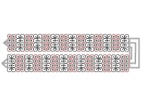
geckocycles said:What do you think of this layout?
52v 20ah Luna brick rebuild.
This is the top of the two bricks put together. The bottom will use neg fuse wire as well. My thoughts were to use only neg fuse wire so if wire slag falls between batteries it won't short out.
2 layers of 8mm x .2mm nickle on everything.
garolittle said:geckocycles said:What do you think of this layout?
52v 20ah Luna brick rebuild.
This is the top of the two bricks put together. The bottom will use neg fuse wire as well. My thoughts were to use only neg fuse wire so if wire slag falls between batteries it won't short out.
2 layers of 8mm x .2mm nickle on everything.
Sweet. That looks awesome. What application/project will it power? I like the 8mm-wide nickel strips because they fit perfectly in between my cell holders.

geckocycles said:garolittle said:geckocycles said:What do you think of this layout?
52v 20ah Luna brick rebuild.
This is the top of the two bricks put together. The bottom will use neg fuse wire as well. My thoughts were to use only neg fuse wire so if wire slag falls between batteries it won't short out.
2 layers of 8mm x .2mm nickle on everything.
Sweet. That looks awesome. What application/project will it power? I like the 8mm-wide nickel strips because they fit perfectly in between my cell holders.
Yes they do fit nicely on the positive cells but the negative will be on top of the holders unfortunately.
Outside of design my biggest problem is weld consistency making sure I don't burn some diameter off the fuse wire at the weld. I have played with resistance soldering with good results but I need more experiments on this thin of wire. The resistance welder tips need cleaning WAY too often for consistent results.
500w Moots Zirkel.
https://endless-sphere.com/forums/viewtopic.php?f=6&t=73143&p=1115397#p1115397
bobmutch said:I'm just learning also so I could have this all wrong : )
bobmutch said:
Good discussion topic.
When you run your busbar Parallel then it is your 10 small fuses that get to carry all the current.
I have to admit I have pondered this question many times. Keep in mind that this battery pack is just a small prototype of my next project which will use Samsung INR cells rated at 20 amps continuous. I will be pulling 50 to 60 A continuous with a maximum of 120 A. That project will have a 20S/20P configuration so here is the math:
Max amps of 120 over a 20P “cell” is 6 amps per cell. The cells are rated at 20 amps continuous so there should be very little “heat” in each cell. The individual fuse wires will be rated to blow at 8-9 amps.
bobmutch said:Hmm, I was under the impression that it is the series connects that needs to be more robust than the parallel connections. Using a properly gauged busbar to connect two 2x5 blocks (one pos up one pos down) and the current is flowing through the busbar then on the other end of the cells you offset by one block and connect two more blocks. So the busbar is the serial connection all the way through.