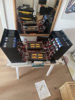
Suzuki GSX-R e899 K2

Bad news … I lost the video material … and again I got controller shut down. I was not able to check the failure because I had to leave the track.
With run 2 and 3 I wait a while and let my brother gone but I caught him before finish line.
So for me the first time I run into the 9 seconds 🤣
 

Attachments

  • IMG_2306.jpeg
    IMG_2306.jpeg
    413.4 KB · Views: 30
  • Like
Reactions: pwd
Again at Bamberg Airport
But without success.
I could not reproduce the failure which leads to the controller shut down.
Even at 140 kph I got spinning wheel and the rear wheel started to dance from side to side.
Put a nice rubber lane to the field 😉.
I also increased the motor phase current to 525Arms and another 75Arms to go.
Well what shall I say, it made a lot of fun at the acceleration point 😀.
I started also to get more and more respect for the power!


To be honest it looked slow in the video. I started from 0 and stopped accelleration when I reached the high of the camera. The video was made from my daughter. She also has to learn how to record 😉. I also activated the Insta360 by pressing the red push button on the cam. But what I didn’t realize was that the cam was in Timelapse mode. So the 4 little runs have a time sequence of around 4 seconds. I also have to learn how to record 🤣
 
Starting now to parameterise the ECU Master ADU Display.
The controller is able to provide some informations via CAN connection. The most important thing is to see the failure and failure code later on.
Actually the display shows an example picture for cars and has no connection to the controller.
Have to build a new picture by controller informations.
 

Attachments

  • IMG_2251.jpeg
    IMG_2251.jpeg
    194.2 KB · Views: 9
Step one is done. The display page was updated.
But I have CAN failure when I connect the controller.
So maybe CAN High and CAN Low change or the data transmission is wrong …
 

Attachments

  • 7c751e05-1f34-4c2f-a147-5b7e9924a399.jpeg
    7c751e05-1f34-4c2f-a147-5b7e9924a399.jpeg
    382.4 KB · Views: 5
And there the story ends.
CAN High from controller showed 0V. CAN Low also 😢.
Therefore I will never seen any information on the display.
 
Yes, I think so. Normally the CAN High should be around 2,5V difference to the CAN Low. But both against 0V are showing 0V. Except the 12V cable.
 

Attachments

  • IMG_2746.jpeg
    IMG_2746.jpeg
    81 KB · Views: 4
A software developer from ECUMASTER (Poland) was online on the ADU display via remote connection (AnyDesk). He checked a lot of parameters, wrote a little test program but also can’t find the problem. With a sniffer we saw now the values coming from the controller but the controller has problems by sending the informations via 1MBit/s where CAN1 of ADU display is working. So we reduce the speed to 500kBit/s and tried to connect the controller ton CAN2 of ADU display. The display said CAN1 and CAN2 are ok via software. But maybe there are problems with their software or the adress where controller send his informations because ECUMASTER is using the same adress for their GPS module. Of course it’s possible to change it but nevertheless no datas are coming in. They want to test it now on their bench and inform me when they find a solution. In the meanwhile I ordered a 13” notebook (convertible) and connected it to the controller.
That worked for sure but means that I have to update the design from the fuel tank cover ..
 

Attachments

  • 43a38668-d6e8-473c-ae7a-9545d5faf27e.jpeg
    43a38668-d6e8-473c-ae7a-9545d5faf27e.jpeg
    406.2 KB · Views: 7
  • dddec172-cb5a-4e01-9955-7b6f1626e133.jpeg
    dddec172-cb5a-4e01-9955-7b6f1626e133.jpeg
    341.5 KB · Views: 7
Fighting with Controller shut downs, when the grip is to good. Have to find out what failure and failure code will be shown. And I am driving on normal landing fields without prep.
 
Little private event with friends
 
Seems to be a hardware problem of ADU display. CAN2 High is showing 0V.
Have to send the display now to Poland for repair.
 
Found the problem …
 

Attachments

  • IMG_2874.jpeg
    IMG_2874.jpeg
    192.6 KB · Views: 10
That’s another issue which has to been solved 😉.
Everything step by step 😉.
The most important thing is that the display received now values. And yes, normally they should stand 0A because the main battery was not switched on due to a failure of one main circuit breaker. I think I will throw them all out!
Only the main circuit breaker inside the controller will be available.
But nevertheless I will bring the 13“ notebook also to the system. So I have something to do over winter time 😀
 
So first step is done
Display and controller showing the same values but display has a little delay.
 

Attachments

  • IMG_2877.jpeg
    IMG_2877.jpeg
    276.3 KB · Views: 1
Something to play for winter time 😀
 

Attachments

  • IMG_2887.jpeg
    IMG_2887.jpeg
    208 KB · Views: 10
Tank cover is changed, 13“ notebook is installed, rear wheel cover is added.
I also got now a sponsoring, so there will come a sticker on my fairing.
Next step will be to update the battery circuit power cables.
 

Attachments

  • 47dc0999-e212-4514-90bf-bce15455b520.jpeg
    47dc0999-e212-4514-90bf-bce15455b520.jpeg
    285.7 KB · Views: 11
  • bf1bbc81-98d8-4496-b20b-ec0eaffd9e06.jpeg
    bf1bbc81-98d8-4496-b20b-ec0eaffd9e06.jpeg
    242.8 KB · Views: 11
  • f42051e3-7657-4bf5-8be0-562055ddde6b.jpeg
    f42051e3-7657-4bf5-8be0-562055ddde6b.jpeg
    295.7 KB · Views: 11
Back
Top