Infineon XCKJ8B116A 12 Mosfet Brushless Controller, stock for 45 Amps peak with 72v.
Model: EC-124110-LYEN EDITION
Stock controller review: http://endless-sphere.com/forums/viewtopic.php?f=4&t=17679
After testing this controller out of a few days I decided it had a lot more potential; and being a power hungry freak, I decided to beef this thing up to the max!
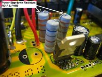
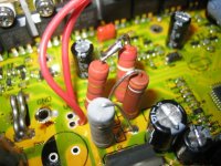
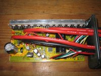
First thing to do was to replaced the power side resistors with 870 ohm 3W total of resistance, which actually came out to 856 tested. This is for running 22S A123's 72.6V nominal. I replaced them with Vishay brand resistors, they are a tad smaller in size compared to the stock ones, but are the same Wattage.
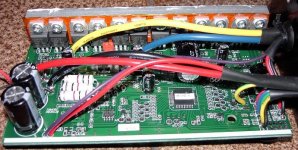
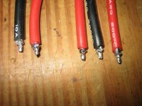
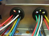
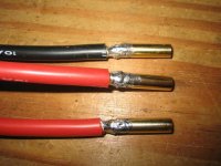
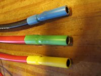
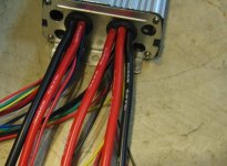
Next thing I did was replaced the 12AWG wire with 10AWG. As I found out after de-soldering the 12AWG wire, the holes in the board are too small for the 10AWG. So it was either drill the holes larger, or modifiy the wire ends. I decided to mod the wire ends. Also the grommit holes at the end of the controller for the wires were too small, I had to drill those out larger and carefully. I used colored heat shrink and 4mm bullet connectors. The 4mm bullets are good for around 75 to 100amps continuious, and higher peaks.
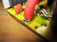
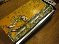
Next was to Pull up the stock trace solder and lay down 2 layers of 12AWG solid copper wire. By my calculations, the 2 stacked layers of 12AWG and the solder, the trace are is now equal to 8 to 9 AWG. Plenty of beef for going to 100 amps or more. I spent a long time on that area.
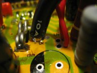
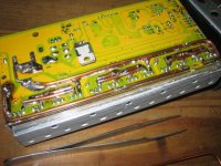
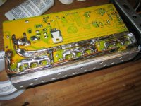
Shunts, What to do? I decided to mod the controller physically, rather then rely on the programming to do the job. I went with 4 shunts total. Thanks to Lyen for hooking me up with a couple spare shunts. Being there is not much room on the top side of the board, I decided on putting the other 2 underneith. Some of you may ask, why not just solder up the shunts instead of adding more shunts? Well, I thought to myself physically having more mass and conductive area for the current to go through is better. 2 shunts are almost equall to 11AWG, and 4 shunts are almost equal to 8AWG.
After finishing these mods, the controller is pulling 100 Amps peak without any settings changed in the programming. The phase current and rated current were still set for 80 and 30. So adding the 2 extra shunts gave me 40 more amps! The programming settings are able to go up to 157 phase and 50 something rated current. I'm guessing the controller can do 120 Amps easy, but 95 is plenty for me. I am also using Arctic silver 5 thermal paste on the mosfet block.
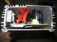
Inside the controller was a tad warm. The controller wasn't getting any good air flow though from the outside. I haven't moved it to the new location for this setup. I measured 55c on the mosfet inside after hammering the throttle for 3 or 4 min. The temps outside were only 65F. Thats pretty cool for here in Texas. I thought to myself the controller may get up to 65C when the temps were 95F this summer. The small wires inside the controller are only rated for 80c. This was on the edge for me, and I had to do something else, to put me in the safe zone in my mind.
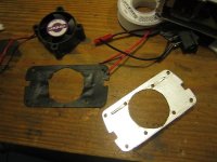
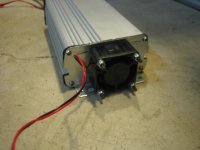
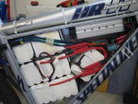
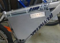
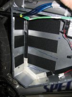
I had to figure out a way to cool this thing under extreme conditions. My new setup is to mount the controller in the center of the bike. The controller sides will be open to the air with my new setup, so that will help out. But I still wanted to make sure I wouldn't ever have problems. I drilled 4 intake holes in the front end plate and cut out a large exhaust hole in the rear plate of the controller. I ordered a 40mm 6.5CFM case fan for the rear. This really turned out well. The suction of air was excellent. The fan runs of 4S off my pack. Which is 13.2v nominal, and just over 12V under throttle load. I have an external switch so I can turn the fan off and on when I want. I have measured around 41c now with using the fan 25% of the time durring the ride. Going easy you don't need the fan on, but it hasn't been over 80F here yet in Texas, and I haven't been hammering the throttle to the extreme yet either for a long period of time.
Model: EC-124110-LYEN EDITION
Stock controller review: http://endless-sphere.com/forums/viewtopic.php?f=4&t=17679
After testing this controller out of a few days I decided it had a lot more potential; and being a power hungry freak, I decided to beef this thing up to the max!
First thing to do was to replaced the power side resistors with 870 ohm 3W total of resistance, which actually came out to 856 tested. This is for running 22S A123's 72.6V nominal. I replaced them with Vishay brand resistors, they are a tad smaller in size compared to the stock ones, but are the same Wattage.
Next thing I did was replaced the 12AWG wire with 10AWG. As I found out after de-soldering the 12AWG wire, the holes in the board are too small for the 10AWG. So it was either drill the holes larger, or modifiy the wire ends. I decided to mod the wire ends. Also the grommit holes at the end of the controller for the wires were too small, I had to drill those out larger and carefully. I used colored heat shrink and 4mm bullet connectors. The 4mm bullets are good for around 75 to 100amps continuious, and higher peaks.
Next was to Pull up the stock trace solder and lay down 2 layers of 12AWG solid copper wire. By my calculations, the 2 stacked layers of 12AWG and the solder, the trace are is now equal to 8 to 9 AWG. Plenty of beef for going to 100 amps or more. I spent a long time on that area.
Shunts, What to do? I decided to mod the controller physically, rather then rely on the programming to do the job. I went with 4 shunts total. Thanks to Lyen for hooking me up with a couple spare shunts. Being there is not much room on the top side of the board, I decided on putting the other 2 underneith. Some of you may ask, why not just solder up the shunts instead of adding more shunts? Well, I thought to myself physically having more mass and conductive area for the current to go through is better. 2 shunts are almost equall to 11AWG, and 4 shunts are almost equal to 8AWG.
After finishing these mods, the controller is pulling 100 Amps peak without any settings changed in the programming. The phase current and rated current were still set for 80 and 30. So adding the 2 extra shunts gave me 40 more amps!
The programming settings are able to go up to 157 phase and 50 something rated current. I'm guessing the controller can do 120 Amps easy, but 95 is plenty for me. I am also using Arctic silver 5 thermal paste on the mosfet block.Inside the controller was a tad warm. The controller wasn't getting any good air flow though from the outside. I haven't moved it to the new location for this setup. I measured 55c on the mosfet inside after hammering the throttle for 3 or 4 min. The temps outside were only 65F. Thats pretty cool for here in Texas. I thought to myself the controller may get up to 65C when the temps were 95F this summer. The small wires inside the controller are only rated for 80c. This was on the edge for me, and I had to do something else, to put me in the safe zone in my mind.
I had to figure out a way to cool this thing under extreme conditions. My new setup is to mount the controller in the center of the bike. The controller sides will be open to the air with my new setup, so that will help out. But I still wanted to make sure I wouldn't ever have problems. I drilled 4 intake holes in the front end plate and cut out a large exhaust hole in the rear plate of the controller. I ordered a 40mm 6.5CFM case fan for the rear. This really turned out well. The suction of air was excellent. The fan runs of 4S off my pack. Which is 13.2v nominal, and just over 12V under throttle load. I have an external switch so I can turn the fan off and on when I want. I have measured around 41c now with using the fan 25% of the time durring the ride. Going easy you don't need the fan on, but it hasn't been over 80F here yet in Texas, and I haven't been hammering the throttle to the extreme yet either for a long period of time.
Attachments
-
 IMG_6179.JPG56.4 KB · Views: 9,262
 -
 IMG_6195.JPG67.7 KB · Views: 9,745
 -
 IMG_6198.JPG57.2 KB · Views: 9,784
 -
 IMG_6199.JPG43.6 KB · Views: 9,744
 -
 IMG_6201.JPG42.5 KB · Views: 9,744
 -
 IMG_6188.JPG47 KB · Views: 9,784
 -
 IMG_6220.JPG65.5 KB · Views: 9,261
 -
 IMG_6223.JPG46.1 KB · Views: 9,261
 -
 IMG_6206.JPG67.9 KB · Views: 9,744
 -
 IMG_6203.JPG70.3 KB · Views: 9,261
 -
 IMG_6204.JPG69.8 KB · Views: 9,745
 -
 IMG_6209-5.jpg86 KB · Views: 9,262
 -
 IMG_6226-5.jpg50.6 KB · Views: 9,262
 -
 IMG_6259.JPG49.1 KB · Views: 9,261
 -
 IMG_6253.JPG40.4 KB · Views: 9,261
 -
 IMG_6258.JPG32.3 KB · Views: 9,261
 -
 IMG_6263-5.jpg86.5 KB · Views: 9,262
 -
 IMG_6276-5.jpg36.7 KB · Views: 9,261
 -
 IMG_6261-5.jpg54.4 KB · Views: 9,236