Roy Von Rogers said:Gary is there any way you could tell me what those battery spring numbers are from Mouser, I'm looking for some also.
+1
Also looking for good springs.
Roy Von Rogers said:Gary is there any way you could tell me what those battery spring numbers are from Mouser, I'm looking for some also.
Jay64 said:just clarifying here, the 534-211 is the smaller of the two, correct?
")
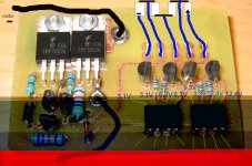
fechter said:This was designed by Randomly. I have not tested it, but see no reason why it won't work.
The number/size of the FETs depends on your maximum current requirement and heat sink size.
manfred59 said:Would it be possible to unite the great BMS with an active cutoff?
It would be fine for my 4 cell BMS which has no controller with break connector.
I could do a layout if anybody could publish a circiut of this solution.

CGameProgrammer said:Guys, I have dead cells! It's been about a year since I last rode my e-bike, and when I tried charging it, one of my 10s6p packs wouldn't charge; the charger returned an error. I'm using the stock DeWalt charger, using the stock BMS only for charging.
I checked the voltages, and one 6p string is 0.1V! The others are all 3.2V or 3.3V.
Is that string definitely dead or might there be some sort of hope for reviving it? That pack was made by effectively just putting six DeWalt packs in parallel so that would be a difficult thing to repair...
Guys,,, you know all that i have great experience with these dewalt packs 8)
There is something i discovered that impressed me alot about these low cells that we easyly declare: dead ....
I had many of them that i kept for me instead of selling them that i tested again.
I was surprized to see that many cells clos eto zero V was still good with capacity and RI !!
I mean... these famous 1 or 2 "bad"... or even low cells that had 0.9V or 0.2V still gaved me 2150mAh and 10 mohm !! ..
and same results with 5 cycles after that!!
I also had a pack that i kept for me that measured 0.8V with every cells between 0.1 and 0.2V that i successfully charged using individual charger/cell and that gaved me 2100mAh ! with Ri between 10 and 13mohm /cell !!
since the last full charge of that pack i let ist to sit for 2 month on my desk and it still measure 34.75V of SOC !
That's why i say these cells are like buletproof and so incredible!
i'm not saying that everybody should keep these to match with their ebike batt project.. but for something like boostpack they are excellent!
If you try to recharge these lower cells, you will see quickly if they survived or not... the really BAD/DEAD cells will just heat up and will not keep their voltage when you remove the current
The best solution to ravive low cells is to begin the charging process at 500mA and when they reach 3.0V you can increase the current.
The DEAD cells will never reach more than 1.5V durin g the 500mA charge process.. the rest should succed.
SO DONT PUT THE LOW "DEAD" CELLS IN THE TRASCAN IMMEDIATLY !
Doc
What I did is a layout for a 4cell LVC, but I need help!Originally, I was going to do a standalone 12V/4s BMS, for an SLA replacement pack setup, but never got around to it. I did work on a 24V/8s full BMS board, with active cutoff, but I don't think I finished it. I'll look around for this version.-- Gary


Doctorbass said:wow.. that's a really clean and nice job you did Gary!!
I wonder have you thsted the max current one single spring can gandle before to heat too much?
I ask because i had the occasion to test the max current of the spring on the original dewalt side cover.. dor balancing.
I measured 1A max before it heat too much and could melt plastic.. and i would recommand max 0.5A..
I know the one you are using are bigger so have you tested a max current?
Doc
GGoodrum said:
I'm really looking forward to following your progress with the VW bus conversion. CGameProgrammer said:This has probably been answered but I can't find it -- If I have two 10s subpacks connected in series (as one 20s pack), can I safely use two DeWalt chargers (and BMS) to charge each 10s subpack simultaneously without disconnecting them from each other (so they're still connected in series)? Or do they have to be disconnected or a diode used? If the latter, I would prefer the diode approach, but have no idea what I'd need to use.
I tested this approach once and it worked fine. The Dewalt Chargers appear to have sufficient isolation from main power.