GGoodrum
1 MW
I decided to start this thread to share my experiences with a123-based packs, in terms of what is really required to get the most out of the cells, how to make packs, how to charge/balance them and how to protect them in use.
The a123-M1 cells were developed by an MIT-spinoff called a123Systems. They use the same LiFePO4 chemistry as many of the emerging Chinese variants, which is inherently much safer than any of the Cobalt and/or Maganese-based Lithium cells. What sets the a123-M1 cells apart is their proprietary use of nanotechnology in the electrode design. This allows these cells to be discharged at very high rates, and also allows them to be charged at very high rates as well, mainly due to a very high "C" rating, and low internal resistance. They are also extremely safe. Unlike othre chemistries, these will not explode if you over-charge or over discharge the cells.
Each cell has a totally usable capacity of 2.3Ah, a nominal voltage of 3.3V per cell and a fully-charged voltage of 3.65V per cell. They are rated for 30C continuous discharge (70A) and over 50C (120A) for up to 10 second "bursts". Most of the Chinese LiFe cells have max discharge rates around 2-3C. What that means is that in order to pull 40-50A out of them, you need packs that are 20Ah, or better. With a123 cells, you could easily pull 40-50A out of a "single-p" 2.3Ah pack. In practical terms, though, you won't get much range on 2.3Ah, but the point is that it doesn't have to be 20Ah. I think 90% of the users out there don't need more than 10Ah, 90% of the time.
When using a123 cells paralleled together, in order to get higher capacities, this also raises the "C" rating even further. In a 4p/9.2Ah configuration, the continuous discharge rating goes up to 280A and the burst current rating to a whopping 480A. This flattens out the discharge "curve" even more. The power delivered is very consistant, all the way up to the end of the capacity, and then it drops off quickly. With every other type of battery I've tried, you can "feel" the performance under load drop as you get closer to the end of the capacity. With these, the power pretty much feels the same 10 seconds from the end as it does in the beginning. If the cells in the pack are well balanced, power at the end will drop so fast, you will think you blew a fuse. Therein lies the only real "weakness" with using a123 cells in an EV application. The only way I'v found to kill these things is by over-discharging. This, of course, is applicable to all Lithium-based batteries, but it is actually easier to do with a123-based packs, due to the fact you don't get any notice that the end of capacity is near.
How to get a123 cells...
You can get bare a123-M1 cells directly from the manufacturer in development kits, but these are quite expensive at about $18 a cell. Many in the RC world, including myself, have tried to get a123Systems to sell us bare cells at some sort of reasonable price, but to no avail. The best I was able to do was to get them down to about $12 a cell, but that was for a quantity of 50,000. These cells were originally developed for Black and Decker's DeWalt brand pro line of 36V power tools. DeWalt bought 10 million a123-M1 cells last year, so even if you added up the total potential number of cells used in the RC and ebike/scooter applications, it would be a statistically miniscule portion of DeWalt's production run.")

DeWalt uses 10 M1 cells in each 36V power pack. I'm not sure why they call them 36V because the nominal voltage per cell is 3.3V. The only time this pack is anywhere close to 36V is fresh off the charger. Anyway, DeWalt sells these packs retail at about $160 each. They also include them, however, as part of combo packages where they will have a couple of power tools and maybe a light, along with two of these packs and a charger, at quite a cost savings over the individually priced items. There are a number of ebay power tool dealers who will break these combo packs apart and sell the pieces separately, including the packs. What this means is that you can buy these 10-cell DeWalt packs off eBay for about $90-$100, shipped. That makes the per cell cost of about $10, much more reasonable. To find these , just do a search on eBay for DeWalt 36V DC9360 and you should get a list of what's currently available.
Building, charging and balancing packs...
Inside the DeWalt packs the 10 cells are connected together in series via welded tabs. The 10-cell bundle is held in place with a pair of molded plastic end caps that also contain some springloaded wires that are used for individual cell moitoring and balancing. There is an embedded battery management system (BMS) that is part of the top half of the case. In order to get at the cells you need to use a Torx T-10 security tool to remove 7 screws that hold the top half of the case to the bottom portion.
Once the screws are removed, you need to unplug the two 5-pin plugs that connect the BMS to the plastic end cases.

There is a temp sensor taped to one of the cells and there are three wires soldered to the output tabs of the 10-cell pack.

You can simply cut the wires off, being careful not to short out the tabs.

You can remove the 10 cells, with the end caps by using a flat-head screwdriver to gently lift under the cells on either end, a bit at a time.

Once out of the main case, the end caps will actually simply pop off. Be careful handling these, however, as the cells are loose at this point, simply held together by the welded tabs. I would be careful handling these, as they tend to want to flop around a lot, and you should remove all rings, etc. Once I caught a loose pack of these, as it was falling off the bench, and the main out tabs arc-welded themselves to my ring and finger.

As you can see below, one of the tabs is quite a bit narrower than the others, which makes this a last resort fuse, if all other means of protection fail. I have no idea high much current it would take to break this connection. I've dead shorted 10-cell packs for up to several seconds and although the results were quite spectacular, this connection never broke. I'm guessing it would take something north of 100A for 10 seconds, or so.

In any case, to keep the cells from flopping around, I like to use a hot glue bead between the cells.

In the RC world, there are several popular methods for building packs. The easiest of these is to take a 10-cell pack, like the one shown above, add balancer plugs, main power leads and the simply shrink wrap the whole package together


This form factor doesn't always fit the models very well, so othre methods are used as well. Here's one that uses clusters of four cells, inline:

I've used this method to make some 16s2p eBike packs, but it is a very time-consuming process.


Initially, these didn't have balancing plugs on them, but I have since gon back and added them. I also think that for EV applications, it is much better to connect cells in parallel first and then connect the parallel blocks in series. The reason for doing this is that you can eliminate the need for any sort of current limiting, beyond what the controller already has, and simply add a big fuse. As I have said in a couple other threads, I recently had a short in a harness that cased a dead short on an 18s5p pack. It melted 12 guage wires and caused the plastic plugs and insulation to catch fire. It took me about 10 seconds to blow out the fire and get the connections apart. To my amazement, not only were the cells fine, they weren't even knocked out of balance.
One of the advantages of using a123-based packs is that you have a lot of flexibilty in how you organize packs, both from a total voltage point-of-view, and in the capacity you need. What really drives configuration, more than anything is how the packs will be charged and balanced. If packs are made in multiples of 4 cells, you can use standard SLA-type chargers. What a123, and other LiFe cells need is to be charged at whatever max rate the cell will handle, until the voltage reaches 3.65V. At that point, the voltage needs to be held there while the current is gradually reduced until it gets down below about 1A. or about 10% of the max rate. You can actually charge an a123 cell/pack in as little as 5 minutes, if you have a big enough charger. It is not usually practical to have a charger that can do more than 10-20A, but still, this high charge rate ability is unique to a123 cells. The max charge rate for Chinese LiFe cells is rarely above about 0.5-1C. Anyway, it turns out most SLA chargers use the same sort of constant current/constant voltage (CC/CV) charging profile that is best for a123 cells. For a 12V SLA, a typical SLA charger will peak out at around 14.5.V. The cutoff voltages for 24V, 36V and 48V SLA chargers are about 29V, 44V and 58V, respectively. The optimum 3.65V/cell CC/CV cutoff voltage for a a 4-cell a123 pack is 14.6V, and for 8-cell, 12-cell and 16-cell packs, the equivalent voltages would be 29.2V, 43.8V and 58.4V, respectively.
What ia standard SLA charger will not do, however, is balance the cells in the pack. SLA-type cells will self balance, at the end of the charge cycle. a123 cells, and most other Lithium-based batteries, need to be "manually" balanced. In the RC world, we have a number of automatic balancers that will typically work with packs from 5-10 cells. Most of these have small microcontrollers that look at the voltage of each cell. If they are all above a certain level (usually around 3.0V...), it will start drawing off 150mA from each of the cells that are above the cell with the lowest voltage. This is exactly how the popular Thunder Power 10-cell TP-210V and AstroFlight 6-cell "Blinky" work. Either of these can work while the pack is being charged, but most of the balancing occurs in the CV mode, as the current is being reduced. Thunder power also has the matching 10-cell TP-210V charger that will charge a 10-cell pack of pretty much anything, up to a 5A rate. It can be linked to the TP-210V balancer which allows the charger to monitor and display the voltage of each individual cell. If it detects that the cells are out of balance by more than .3V per cell, it will automatically swith to a "Balance Charge" mode, where it cuts the charge current to .3A, until the cells are balanced again.
The trend these days with RC chargers is to either integrate the balancing and charging functions, or to charge the cells independently. The FMADirect BalancePro HD uses an integrated cable that will independently charge up to 6 a123 cells at a max 10A rate. It has a USB port that can be connected to a PC for monitoring the charge process, but no display on the unit itself. This would be a great solution if it were good for more cells, and had an integrated display. The new Schulze 7-36-8 will actually charge up to 14 a123 cells in series at a max rate of 7A, but oddly, it will only auto-balance packs up to 8 cells.
In any case, thought needs to be put into how a123 packs will be balanced and charged before a final pack and/or subpack size is selected. In my case, for my own use, and for the packs I'm doing for my local conversion business, I decided that doing a 10-cell subpack configuration makes the most sense. This is for a couple of reasons. The main one is because I've found it is far easier, and a lot quicker, to build packs based on how they come out of the DeWalt packs. I find I can save even more time by making use of the plastic end caps with all the existing balancing connections. With pre-made harnesses for standard RC balancer plugs, I can completely teardown 4 DeWalt packs, hot-glue them together, plug in the balancer harness, solder main power leads and shrinkwrap the whole pack with heavy-duty rubberized shrink tubing in well under an hour. That ends up being a 10s4p, 33V/9.2Ah, subpack that weighs 7 pounds 9 ounces.


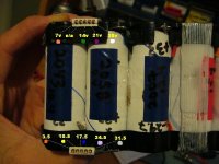
With the test pack shown above, I actually configured it as two 10s2p packs, stuck side-by-side. The balancer wires for each 10s2p pair are brought out separately. One side has a match set of connectors, which allows both sets to be paralleled together by connecting the 2nd set of balancer plugs into this matching set. An external main power harness is used to connect the main leads in parallel. I did it this way because it allows me to disconnect the 2nd set of balancer plugs from the first, and wire these two 10s2p subpacks into a 20s2p configuration, and use it as a "booster pack" to add capacity to my normal 20s4p configuration I'm trying to standardize on for most of my bikes.
For now, my charging and balancing solution is to use a pair of TP-1010C/TP-210V charger/balancer combos, one with each 10s4p subpack. It takes about two hours to completely charge and balance the complete 20s4p setup. Since the TP-1010C, like all RC-based chargers, are designed to run off 12-15VDC, I have them connected to a 25A power supply I got at Radio Shack.
Protection...
As I said earlier, the only current limit protection I think that a123-based pack need is a big fuse. Most, if not all, ebike controllers already have current limiting functions built-in. That simplifies a123 BMS requirements significantly. All that is really required is protection against over-discharging the cells, which is the only way to really kill these things. I know most controllers also have LVC functions that can be "tweaked", but LV protection really needs to be done at the cell/cell block level. Otherwise, you might have a case with a grossly out-of-balance pack where most cells are well above the limit and one is below and thus damaging the cell.
Some have been using the BMS in the DeWalt packs, mainly by cpying the resistor network in one of the tools in order to enable it. The problem is these seem to be overly tempermental, and, more importantly, I haven't seen anyone be able to pull any more than about 20A through them. As I said, I don't hink we need any additional current limiting, just LVC protection at the cell/block level.
Another way to simplify this even further is to not include a positive cutoff at the pack level, which would require multiple high-power FETS, heat sinks, driver logic, etc. What Bob Mcree came up with in the Technical Forum's schematic thread, to satisfy my desire for as simple and as low-cost a circuit as possible, is one that uses two chips and a resistor for each channel that simply drives an opto-coupled output low when the cell voltage drops below 2.7V. The outputs from multiple circuits can be ganged together and then wired into the "Brake Inhibit" line on any Clyte controller. That way if any block of cells falls below the cutoff, the controller will cut power.

The reason for 2.7V is because the chip comes pre-calibrated to this value. The next one down is 2.1V. It isn't all that critical because when you get to that point, the voltage is goig to drop very quick. I have noticed under load, my a123-based setups will stay rock solid at around 3.1V per cell with a 40A load, all the way up to a few seconds before you are at the end of the capacity (usually 2250-2300 mAh per cell...). At that point, if you keep the load on, the voltage will drop a very quick rate. It would literally only take about 15-20 seconds to completely kill a cell if the load is not removed. What an efective LVC needs to do is to detect the start of that rapid fall. I think anything in the 2.1-2.9V will work fine. I believe using 2.7V is perfect, as it should give you a bit more "get home" capability if the load is backed off, which will cause the voltage drop to be reduced for the lesser load, which in turn raises the the voltage in each cell above the cutoff limit.
I have now had boards made for a 10-cell version of Bob's simple LVC design. Two are shown below:

They have matching connectors and can be plugged into the 10s4p subpack's balancer plugs. Two of these boards are required for my 20s4p setups.

I have now also completed another version of this LVC board that also incorporates the Dewalt balancer plug-to RC balancer plug cross-coupling, which eliminates the need for the hand-crafted balancing harness. This will significantly reduce my pack constuction time.

Two of these boards will be used with each 10s4p subpack, but only one will be populated with the LVC parts.
As I said, I'm really doing this for my own use, plus my local work, but I eventaully will probably add both boards, and 10s4p pack construction kit to my RC website. In the meantime, if anybody is interested in getting any of these, for a nominal cost, PM or email me.
-- Gary
The a123-M1 cells were developed by an MIT-spinoff called a123Systems. They use the same LiFePO4 chemistry as many of the emerging Chinese variants, which is inherently much safer than any of the Cobalt and/or Maganese-based Lithium cells. What sets the a123-M1 cells apart is their proprietary use of nanotechnology in the electrode design. This allows these cells to be discharged at very high rates, and also allows them to be charged at very high rates as well, mainly due to a very high "C" rating, and low internal resistance. They are also extremely safe. Unlike othre chemistries, these will not explode if you over-charge or over discharge the cells.
Each cell has a totally usable capacity of 2.3Ah, a nominal voltage of 3.3V per cell and a fully-charged voltage of 3.65V per cell. They are rated for 30C continuous discharge (70A) and over 50C (120A) for up to 10 second "bursts". Most of the Chinese LiFe cells have max discharge rates around 2-3C. What that means is that in order to pull 40-50A out of them, you need packs that are 20Ah, or better. With a123 cells, you could easily pull 40-50A out of a "single-p" 2.3Ah pack. In practical terms, though, you won't get much range on 2.3Ah, but the point is that it doesn't have to be 20Ah. I think 90% of the users out there don't need more than 10Ah, 90% of the time.
When using a123 cells paralleled together, in order to get higher capacities, this also raises the "C" rating even further. In a 4p/9.2Ah configuration, the continuous discharge rating goes up to 280A and the burst current rating to a whopping 480A.
How to get a123 cells...
You can get bare a123-M1 cells directly from the manufacturer in development kits, but these are quite expensive at about $18 a cell. Many in the RC world, including myself, have tried to get a123Systems to sell us bare cells at some sort of reasonable price, but to no avail. The best I was able to do was to get them down to about $12 a cell, but that was for a quantity of 50,000. These cells were originally developed for Black and Decker's DeWalt brand pro line of 36V power tools. DeWalt bought 10 million a123-M1 cells last year, so even if you added up the total potential number of cells used in the RC and ebike/scooter applications, it would be a statistically miniscule portion of DeWalt's production run.
DeWalt uses 10 M1 cells in each 36V power pack. I'm not sure why they call them 36V because the nominal voltage per cell is 3.3V. The only time this pack is anywhere close to 36V is fresh off the charger. Anyway, DeWalt sells these packs retail at about $160 each. They also include them, however, as part of combo packages where they will have a couple of power tools and maybe a light, along with two of these packs and a charger, at quite a cost savings over the individually priced items. There are a number of ebay power tool dealers who will break these combo packs apart and sell the pieces separately, including the packs. What this means is that you can buy these 10-cell DeWalt packs off eBay for about $90-$100, shipped. That makes the per cell cost of about $10, much more reasonable. To find these , just do a search on eBay for DeWalt 36V DC9360 and you should get a list of what's currently available.
Building, charging and balancing packs...
Inside the DeWalt packs the 10 cells are connected together in series via welded tabs. The 10-cell bundle is held in place with a pair of molded plastic end caps that also contain some springloaded wires that are used for individual cell moitoring and balancing. There is an embedded battery management system (BMS) that is part of the top half of the case. In order to get at the cells you need to use a Torx T-10 security tool to remove 7 screws that hold the top half of the case to the bottom portion.
Once the screws are removed, you need to unplug the two 5-pin plugs that connect the BMS to the plastic end cases.
There is a temp sensor taped to one of the cells and there are three wires soldered to the output tabs of the 10-cell pack.
You can simply cut the wires off, being careful not to short out the tabs.
You can remove the 10 cells, with the end caps by using a flat-head screwdriver to gently lift under the cells on either end, a bit at a time.
Once out of the main case, the end caps will actually simply pop off. Be careful handling these, however, as the cells are loose at this point, simply held together by the welded tabs. I would be careful handling these, as they tend to want to flop around a lot, and you should remove all rings, etc. Once I caught a loose pack of these, as it was falling off the bench, and the main out tabs arc-welded themselves to my ring and finger.
As you can see below, one of the tabs is quite a bit narrower than the others, which makes this a last resort fuse, if all other means of protection fail. I have no idea high much current it would take to break this connection. I've dead shorted 10-cell packs for up to several seconds and although the results were quite spectacular, this connection never broke. I'm guessing it would take something north of 100A for 10 seconds, or so.
In any case, to keep the cells from flopping around, I like to use a hot glue bead between the cells.
In the RC world, there are several popular methods for building packs. The easiest of these is to take a 10-cell pack, like the one shown above, add balancer plugs, main power leads and the simply shrink wrap the whole package together
This form factor doesn't always fit the models very well, so othre methods are used as well. Here's one that uses clusters of four cells, inline:
I've used this method to make some 16s2p eBike packs, but it is a very time-consuming process.
Initially, these didn't have balancing plugs on them, but I have since gon back and added them. I also think that for EV applications, it is much better to connect cells in parallel first and then connect the parallel blocks in series. The reason for doing this is that you can eliminate the need for any sort of current limiting, beyond what the controller already has, and simply add a big fuse. As I have said in a couple other threads, I recently had a short in a harness that cased a dead short on an 18s5p pack. It melted 12 guage wires and caused the plastic plugs and insulation to catch fire. It took me about 10 seconds to blow out the fire and get the connections apart. To my amazement, not only were the cells fine, they weren't even knocked out of balance.
One of the advantages of using a123-based packs is that you have a lot of flexibilty in how you organize packs, both from a total voltage point-of-view, and in the capacity you need. What really drives configuration, more than anything is how the packs will be charged and balanced. If packs are made in multiples of 4 cells, you can use standard SLA-type chargers. What a123, and other LiFe cells need is to be charged at whatever max rate the cell will handle, until the voltage reaches 3.65V. At that point, the voltage needs to be held there while the current is gradually reduced until it gets down below about 1A. or about 10% of the max rate. You can actually charge an a123 cell/pack in as little as 5 minutes, if you have a big enough charger. It is not usually practical to have a charger that can do more than 10-20A, but still, this high charge rate ability is unique to a123 cells. The max charge rate for Chinese LiFe cells is rarely above about 0.5-1C. Anyway, it turns out most SLA chargers use the same sort of constant current/constant voltage (CC/CV) charging profile that is best for a123 cells. For a 12V SLA, a typical SLA charger will peak out at around 14.5.V. The cutoff voltages for 24V, 36V and 48V SLA chargers are about 29V, 44V and 58V, respectively. The optimum 3.65V/cell CC/CV cutoff voltage for a a 4-cell a123 pack is 14.6V, and for 8-cell, 12-cell and 16-cell packs, the equivalent voltages would be 29.2V, 43.8V and 58.4V, respectively.
What ia standard SLA charger will not do, however, is balance the cells in the pack. SLA-type cells will self balance, at the end of the charge cycle. a123 cells, and most other Lithium-based batteries, need to be "manually" balanced. In the RC world, we have a number of automatic balancers that will typically work with packs from 5-10 cells. Most of these have small microcontrollers that look at the voltage of each cell. If they are all above a certain level (usually around 3.0V...), it will start drawing off 150mA from each of the cells that are above the cell with the lowest voltage. This is exactly how the popular Thunder Power 10-cell TP-210V and AstroFlight 6-cell "Blinky" work. Either of these can work while the pack is being charged, but most of the balancing occurs in the CV mode, as the current is being reduced. Thunder power also has the matching 10-cell TP-210V charger that will charge a 10-cell pack of pretty much anything, up to a 5A rate. It can be linked to the TP-210V balancer which allows the charger to monitor and display the voltage of each individual cell. If it detects that the cells are out of balance by more than .3V per cell, it will automatically swith to a "Balance Charge" mode, where it cuts the charge current to .3A, until the cells are balanced again.
The trend these days with RC chargers is to either integrate the balancing and charging functions, or to charge the cells independently. The FMADirect BalancePro HD uses an integrated cable that will independently charge up to 6 a123 cells at a max 10A rate. It has a USB port that can be connected to a PC for monitoring the charge process, but no display on the unit itself. This would be a great solution if it were good for more cells, and had an integrated display. The new Schulze 7-36-8 will actually charge up to 14 a123 cells in series at a max rate of 7A, but oddly, it will only auto-balance packs up to 8 cells.
In any case, thought needs to be put into how a123 packs will be balanced and charged before a final pack and/or subpack size is selected. In my case, for my own use, and for the packs I'm doing for my local conversion business, I decided that doing a 10-cell subpack configuration makes the most sense. This is for a couple of reasons. The main one is because I've found it is far easier, and a lot quicker, to build packs based on how they come out of the DeWalt packs. I find I can save even more time by making use of the plastic end caps with all the existing balancing connections. With pre-made harnesses for standard RC balancer plugs, I can completely teardown 4 DeWalt packs, hot-glue them together, plug in the balancer harness, solder main power leads and shrinkwrap the whole pack with heavy-duty rubberized shrink tubing in well under an hour. That ends up being a 10s4p, 33V/9.2Ah, subpack that weighs 7 pounds 9 ounces.
With the test pack shown above, I actually configured it as two 10s2p packs, stuck side-by-side. The balancer wires for each 10s2p pair are brought out separately. One side has a match set of connectors, which allows both sets to be paralleled together by connecting the 2nd set of balancer plugs into this matching set. An external main power harness is used to connect the main leads in parallel. I did it this way because it allows me to disconnect the 2nd set of balancer plugs from the first, and wire these two 10s2p subpacks into a 20s2p configuration, and use it as a "booster pack" to add capacity to my normal 20s4p configuration I'm trying to standardize on for most of my bikes.
For now, my charging and balancing solution is to use a pair of TP-1010C/TP-210V charger/balancer combos, one with each 10s4p subpack. It takes about two hours to completely charge and balance the complete 20s4p setup. Since the TP-1010C, like all RC-based chargers, are designed to run off 12-15VDC, I have them connected to a 25A power supply I got at Radio Shack.
Protection...
As I said earlier, the only current limit protection I think that a123-based pack need is a big fuse. Most, if not all, ebike controllers already have current limiting functions built-in. That simplifies a123 BMS requirements significantly. All that is really required is protection against over-discharging the cells, which is the only way to really kill these things. I know most controllers also have LVC functions that can be "tweaked", but LV protection really needs to be done at the cell/cell block level. Otherwise, you might have a case with a grossly out-of-balance pack where most cells are well above the limit and one is below and thus damaging the cell.
Some have been using the BMS in the DeWalt packs, mainly by cpying the resistor network in one of the tools in order to enable it. The problem is these seem to be overly tempermental, and, more importantly, I haven't seen anyone be able to pull any more than about 20A through them. As I said, I don't hink we need any additional current limiting, just LVC protection at the cell/block level.
Another way to simplify this even further is to not include a positive cutoff at the pack level, which would require multiple high-power FETS, heat sinks, driver logic, etc. What Bob Mcree came up with in the Technical Forum's schematic thread, to satisfy my desire for as simple and as low-cost a circuit as possible, is one that uses two chips and a resistor for each channel that simply drives an opto-coupled output low when the cell voltage drops below 2.7V. The outputs from multiple circuits can be ganged together and then wired into the "Brake Inhibit" line on any Clyte controller. That way if any block of cells falls below the cutoff, the controller will cut power.
The reason for 2.7V is because the chip comes pre-calibrated to this value. The next one down is 2.1V. It isn't all that critical because when you get to that point, the voltage is goig to drop very quick. I have noticed under load, my a123-based setups will stay rock solid at around 3.1V per cell with a 40A load, all the way up to a few seconds before you are at the end of the capacity (usually 2250-2300 mAh per cell...). At that point, if you keep the load on, the voltage will drop a very quick rate. It would literally only take about 15-20 seconds to completely kill a cell if the load is not removed. What an efective LVC needs to do is to detect the start of that rapid fall. I think anything in the 2.1-2.9V will work fine. I believe using 2.7V is perfect, as it should give you a bit more "get home" capability if the load is backed off, which will cause the voltage drop to be reduced for the lesser load, which in turn raises the the voltage in each cell above the cutoff limit.
I have now had boards made for a 10-cell version of Bob's simple LVC design. Two are shown below:
They have matching connectors and can be plugged into the 10s4p subpack's balancer plugs. Two of these boards are required for my 20s4p setups.
I have now also completed another version of this LVC board that also incorporates the Dewalt balancer plug-to RC balancer plug cross-coupling, which eliminates the need for the hand-crafted balancing harness. This will significantly reduce my pack constuction time.
Two of these boards will be used with each 10s4p subpack, but only one will be populated with the LVC parts.
As I said, I'm really doing this for my own use, plus my local work, but I eventaully will probably add both boards, and 10s4p pack construction kit to my RC website. In the meantime, if anybody is interested in getting any of these, for a nominal cost, PM or email me.
-- Gary