Throttle Behavior

Very nice in Eugene today and I took my first real ride since modifying the 2017 controller. Rode about 20 miles and put it through all the various pedal/throttle tests in PAS 0 through 9. As far as I could tell it functioned the same as the 2016 controller that was on my tadpole trike.
 
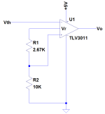
Hey guys, running with @fechter theme of a comparator, I've got several projects with the TLV3011 and thinking it could get us to a very simple circuit (Vth = throttle; Vo open-drain output to wire-or to the pedal cadence sensor):


Throttle2.png
 
That should work.

You could use any open drain/collector comparator and divide the 5v supply to set the trigger point. The 5v seems well regulated. If there was a part with a 1v reference, then you could skip the resistors.
 
Unfortunately the only open-drain comparators I found that provide for the internal reference to be connected to the noninverting input were all above 1.18V.

I've got the TLV3011's laying around and prefer a reference over a supply for comparators but if I were pinching pennies I'd likely just go with using the supply into a divider in this case since accuracy and drift will still be likely good enough. Regardless, IMO either is much better than feeding a bipolar base and won't require any adjusting.

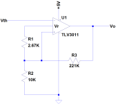
Even though it adds a third resistor and isn't terribly important here, I'm thinking hysteresis too....


Throttle3.png
 
I don't think it will need any hysteresis. It would be hard to hold the throttle right at the trigger point enough to make noise a problem.

The other disadvantage of using a comparator is you need to tap into the 5v supply. One more wire to hook up. But that one is easily accessible on the PAS connector. I can envision a short pigtail cable with a male and female JST connector that simply plugs in line with the existing PAS connector. The circuit is tiny, and could be integrated with the connector. Then you only need to tap into the blue throttle wire.
 
I agree with you about it not needing hysteresis. Even if you get chatter it likely wouldn't make much difference, it will see it as the pedals moving just before the throttle operates. It's just good practice ;-}

I am thinking like you that aside from the throttle wire it easy enough to tap into the cadence sensor connector and I like the idea of something that just plugs in if there's is room for the additional connectors. Do you know the part number(s) for the connectors?

Another thought I had is since the circuit is potentially tiny, under 1/4", to use some good small flexible stranded wire to the circuit but to pot it in the cavity made into the potting that needs to be removed to get to the blue wire. Just a thought and likely more sense if we're splicing into the sensor wires instead of using the connectors. Your thought of integrating it with the connectors is the best if it will fit.
 
Good job on yours! I really appreciate the connector info and will be picking up a pair.

Next step for me is to order another controller to modify... I'm looking forward to fixing this once and for all on my bike!
 
That looks good fechter, small and neat. Looking forward to your test results. :D

EDIT: I tried these parts: Mouser Darlington Transistor, P/N 583-KSP13, and a Mouser Resistor, P/N 71-PTF56100K00TXEK

Mine didn't work, perhaps not the right parts to use, or I hooked them up wrong, or had a bad connection.
 
Very good point about the ratiometric relationship... Sold! I have to buy resistors anyway so I think I'll also just go with whatever open-drain comparator - I have the TLV3011's laying around but I'm keeping an open mind!

I've got a blown controller laying around and started digging into the potting just to see if that was going to be an issue. It's much easier than I expected...
 
I was able to finally install the Darlington circuit on mine. It works but if I advance the throttle so it just barely starts the motor then pedal, I can still get the bucking problem. I can most likely fix this by raising the throttle min voltage in the Bafang programming software. I haven't road tested it yet, so not sure if it needs fixing or not. As the motor heats up, the threshold voltage will drop slightly and reduce the problem. It's only a very small section of the throttle range that does this and you have to try hard to make it happen.

I'll post pics later...
 
I also got a tiny bit of that same issue from my testing, but then I took a ride on my other trike, which has an older (meaning good) BBS02, and if you barely use the throttle there is that same issue. I think in real use, we don't try to "barely" use the throttle, so we don't spend enough time in the ultra low throttle usage position to even notice the transition.

Had another nice ride yesterday, about 16 miles, and am still very pleased with the results of the modification.
 
Makes sense with the high VBE of the darlington. It will be interesting to hear if it's still an issue after raising the throttle minimum in the parameters.

I'm planning on this for now:


Throttle4.png
 
Just got back from road testing and it's good!

I had to reprogram the PAS settings back to normal and I increased the throttle min voltage from 1.0 to 1.1v in the software. This took care of the low end issue and the transition from PAS to throttle seems very smooth and everything works now. If I'm in PAS and it starts going too fast, I can barely give some throttle and it will drop the speed. If I let off the throttle while pedaling, the PAS kicks in right away.

I still don't like the way the PAS keeps the motor going after you stop pedaling, but without a torque sensor, this is how it needs to work. I'm just really not used to it since I disabled it when I first got it.

In off road situations, I can just use the throttle like I'm used to and not worry about getting launched over the side of a cliff.
 
Rassy said:
If you missed it in other discussions, while using PAS, a very slight push backwards when you quit pedaling immediately stops the motor. For me it became almost automatic when shifting, even doing it when just pedaling along with no assist.

I didn't know that. I'll give it a try.

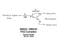
I updated the DIY thread with the details for the Darlington circuit and how to install.
https://endless-sphere.com/forums/viewtopic.php?f=28&t=93977&sid=86ba5c55e5986dd1b354688c8cc0068a
Installation would be similar for the other proposed circuits.
Here's what I ended up with:

Darlington Circuit.jpg

KSP13BU is about the least expensive in a TO92 package ($.32ea) and the resistor is $.10ea.
 
There are two blue wires coming in on that cable with the throttle signal - one is just a little lighter in shade than the other and it goes into the third from the left pin on the controller board (looking at it edge towards us) - the slightly darker one goes into the right hand side pin.

Which one is the throttle signal?
 
There's also a green one - at least in mine. I don't have all the potting off so it may be on a different cable but the light blue one is on the same.. I think...
 
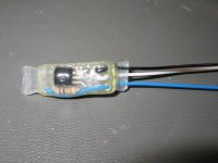
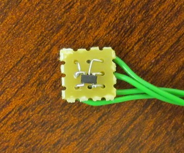
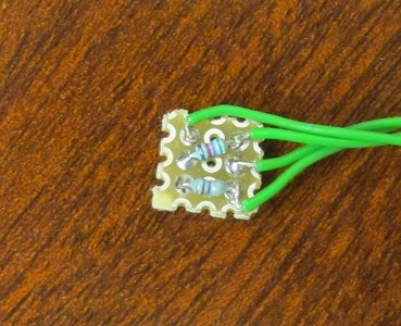
I got some time and built my little comparator board:

i-LWb2wsc-S.jpg


i-BS9vjmv-S.jpg


Hopefully I will get around to installing before too long....
 
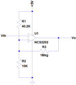
NCS2202 - open drain rail-to-rail in/out

Already had some laying around and very familiar with them. I measured my throttle and found that no throttle was ~0.88V and so split the difference between the target BBSHD throttle threshold of 1.1V and have the comparator detect threshold at just shy of 1.0V. Very eager to see how it works.

Nice and small (~1cm x 1cm) and wasn't too bad to solder up with the right tools.
 
Back
Top