Tostino's water cooled 36 fet infinion

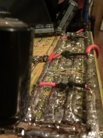
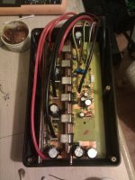
I put kapton tape on the ends of the low side fet blocks, and that seemed to provide some pretty good protection.

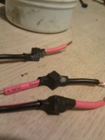
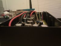
The material on the back is a cut up mouse pad. I thought that would work pretty good because it adds some spring.

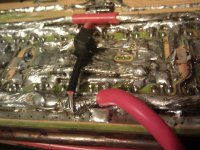
I had some mis-sized shunts, and I had to kinda build that bridge to get the shunt connected properly. Looks like it will work well.
 
hillzofvalp said:
very interesting. *crosses fingers* getting close?
You tell me...
 

Attachments

  • IMG_20120918_234645 (Large).jpg
    IMG_20120918_234645 (Large).jpg
    292 KB · Views: 1,408
  • IMG_20120918_235019 (Large).jpg
    IMG_20120918_235019 (Large).jpg
    254.9 KB · Views: 1,408
  • IMG_20120918_235035 (Large).jpg
    IMG_20120918_235035 (Large).jpg
    181.7 KB · Views: 1,408
So, i've got almost everything ready to go... I am having some issues trying to wire up my controller for my CA, the CA had a speed sensor, but that was broken in the accident, so I wanted to try and hook up the speed sensing through my controller but am having trouble finding info on how. Lots forgotten since I did this last.

Also, my R12 is at 1150 ohms, is there an easy way to know what value I need to lower that to to enable regen on 24s?

I ordered torque arms, a throttle, and a 3 speed switch from Methods, and those just came in last night. Also got a 20s hardcase lipo pack from a member on the forums, which I will be purchasing some additional packs for to make it 24s.

I'm excited to get this actually working.
 
It's time for another update!
I don't have any pics at the moment (at work), but i'll post em later.
I had some free time, and a dremel, so yesterday I got to modifying the case. I notched out a slot for the high power, and signal wires, and created 8 holes for the water cooling tubing to get into the case. It fits like a glove.

I also strain relieved the groups of wires coming out of the case. I had some 1/2" rubber tubing which I sliced down the side, and slipped that over the power handling wires, then I used a hose clamp to tighten down so no individual wire could be pulled. That goes on the inside of the case. I did the same (with smaller tubing and hose clamp for the signal wires).

I still haven't found any info on the CA connection for speed sensing. It was probably 4 years ago I did it for my first controller, and I can't quite seem to find the resources I had used that time.

Does it just get hooked up to one of the motor hall sensors?

I'll get some pics when I get home today.
 
Thanks! I got that wired up, but i'll have to test later (about to go on vacation).

So, here are the pictures:
IMG_20121001_212037.jpg

View attachment 4

IMG_20121001_212224.jpg

IMG_20121001_212240.jpg


And I was looking through my closet, and I ran across this on the top shelf, all packaged up still... I completely forgot that I had ordered one!
IMG_20121001_212441.jpg

IMG_20121001_212449.jpg
 
Small update, I had ordered spokes and a rim, and last week I tried to lace up my motor. However, it turns out that the listed ERD of the rim was different than the actual ERD. Very fuckin' helpful. The spokes were 7mm too long. I didn't even notice until I had everything in place, and I started tightening everything down.

So after that, I pulled it all apart and sent those spokes back for a refund, measured the actual rim ERD, and bought the right length spokes the same night.

They came in today, so I hope I will have some time tomorrow to lace it up. I also ordered some of the 1.2uf 250v ceramic caps that I saw Methods had used on one of his 24 fet controllers. I knew that I needed to add some ultra low ESR caps to this controller, just didn't know what would be best until this point.
Edit: here is the link for anyone interested: http://www.mouser.com/Search/ProductDetail.aspx?qs=uhYMDJu9YpcRmIEJdyUoGw%3D%3D

Last night I had some free time, so I soldered some connectors to the controller. I got the power and phase anderson's soldered. Had to use a torch to get them hot enough XD.

Also, I put silicone on the wire outlet, and around both side covers, and added about 150ml of ATF to the motor. I still need to drill a very very small vent/fill hole. Looks like nothing is leaking, even through the bearing (tested just to see if it would).

I'm excited to get this done!
 
Here are some pics. I went with some giant connectors for the battery... three 10g for +, and one 8g and 1 10g for -.
Also soldered on connectors for the phase wires (75a anderson's).

Wheel is all laced up, but untrue as can be because I can't find my damn spoke wrench. May just take it to a bike shop to do it, because it is kinda pissing me off, and i'm not very good at it.
 

Attachments

  • IMG_20121022_190405.jpg
    IMG_20121022_190405.jpg
    121.8 KB · Views: 1,403
  • IMG_20121024_205330.jpg
    IMG_20121024_205330.jpg
    183.8 KB · Views: 1,403
  • IMG_20121024_205347.jpg
    IMG_20121024_205347.jpg
    197.7 KB · Views: 1,403
  • IMG_20121024_205408.jpg
    IMG_20121024_205408.jpg
    162.8 KB · Views: 1,403
Cool you should look into making the fets switch faster.
 
Well, got my wheel on the bike and trued up... had to do it myself.

I used an old 14s 8ah battery pack in a backpack, so much lower voltage and C rate than what I will be using.
I got all the connectors on for everything but the CA, and took it for a test spin up and down the street, and all over my yard (17 acres). I did a lot of low speed in sugar sand. Used prolly 4ah doing hard acceleration (with no water cooling hooked up yet), and when I opened the controller up, the heat syncs and fets were cool as a cucumber.

The amp limit is programmed pretty damn low I can tell. I'll have to get the CA hooked up tomorrow to see. Probably only getting 60a out of it.
 
Methods ran his 24 FET controllers on a Cromotor at 150A on the dyno and wasn't able to get his controller warm, I doubt you will have any issues with 36 FET. You won't need water cooling with your current motor. With a really hard to drive motor it could come in handy. Either way 36 FETs is nice to have, you shouldn't have to worry about it.
 
Yeah, but I also have no cooling for the syncs at all without water. It's not connected to a metal case like most controllers, so I don't get the benefit of that. It'd be exactly like anyone else running their controller without the case.

But yeah, I doubt i'll need water cooling on it at all until I blow this motor up and get a new one.

It was kinda nice to see it actually work after all of this time and effort.
 
Got my CA hooked up yesterday, and the bike put together much better than on Saturday.

The battery I was using was one of the packs I was using a couple years ago on my old recumbent bike... there are some issues to say the least.

Looks like 10v voltage drop for a 25a load. Crazy bad. When these were working properly, they would do 110a at a 3v drop.

So I was only able to get 30-35a peak from this crappy pack. Annoying to say the least.

Guess i'll have to work on getting my new battery pack hooked up sooner rather than later. I want to see this thing at higher power.
 
Well today was shitty...

I just got home from work maybe 20 min ago, and started tightening things down. I wanted to make sure regen wasn't screwing with the dropouts.
So I am on and off the throttle with the wheel in the air, hitting regen to see if the axle moves, and then I hear something pop, and the wheel comes to a dead stop. I think to myself "oh shit". and try and spin the wheel by hand, no go, two of the phases are shorted (could tell from the way it resisted). I then unplugged the controller, and tried to spin the wheel, and all was normal... My heart sank.

Well, it was on the low side, and I couldn't see anywhere on the traces that it had shorted, so I pulled the heat sink off the back to find this:
IMG_20121029_191756 (Medium).jpg

IMG_20121029_191539 (Medium).jpg

I couldn't see any damage to the fets, but that doesn't mean they are fine... Then I thought to check if they were still shorted. It turns out they weren't. Now that I knew that, I decided to try hooking it back up to the motor for a second to try spinning it. It worked flawlessly.


Now I need to figure out why the frock the Kapton tape rubbed through and shorted.

I'm just glad the fets didn't blow =).
 
tostino said:
Well today was shitty...


Now I need to figure out why the frock the Kapton tape rubbed through and shorted.

I'm just glad the fets didn't blow =).
Edit: the fets groups were wiggling on the heat sinks. Could be thermal expansion remember the heat sink vs the fet soldered piece of copper will heat at different rates.
 
I'm sure that was it.. There were probably small air bubbles in the tape that burst as the sinks moved against each other. Just a little unsettling. Both were room temperature when it happened, so I doubt it had to do with heating.
 
tostino said:
I'm sure that was it.. There were probably small air bubbles in the tape that burst as the sinks moved against each other. Just a little unsettling. Both were room temperature when it happened, so I doubt it had to do with heating.
What Im getting at is when you use it one expands faster as the fets heat up and this causes the rubbing. Unless you never run it before this happend?
Anyways you got lucky lol. These kinds of things happend and Im one who has had 1000s of design suprises like this :)
 
I did run it a little before this... maybe an hour total.
I'd say it was some kind of luck.... on one hand, my old battery pack is now so shitty it can hardly put out more than 30 amps, when it used to do 120 with hardly any sag, so it's lucky that it was not able to provide enough current to even heat up the fets in the event of a short... it is still pretty unlucky that the pack is as crappy as it is now.

Anyways, thanks for the input, good to know I'm not always talking to an echo chamber :).
 
I got those caps in last night.

While I was fixing the heat sink, I also soldered the caps in place. Added a total of 15.6 uH 250v caps to the board.
Also decided to half my shunt resistance to .25 mohm, because they probably would have de-soldered themselves at higher power levels when it was .5 mohm.

Took the bike up and down the street, 70a peak at 50v... it's fun =).
 

Attachments

  • IMG_20121030_213541 (Medium).jpg
    IMG_20121030_213541 (Medium).jpg
    188.9 KB · Views: 1,600
  • IMG_20121030_213441 (Medium).jpg
    IMG_20121030_213441 (Medium).jpg
    165.8 KB · Views: 1,600
  • IMG_20121030_204637 (Medium).jpg
    IMG_20121030_204637 (Medium).jpg
    96.9 KB · Views: 1,600
Good stuff. What pump are you using? Whats the flow? Which way do you have your pump set up, is it a thermoswitch controlled?
Any data on before and after amps temps etc.?
 
agniusm said:
Good stuff. What pump are you using? Whats the flow? Which way do you have your pump set up, is it a thermoswitch controlled?
Any data on before and after amps temps etc.?
As of right now, I have absolutely none of the water stuff set up. I had to order a smaller radiator so I could actually fit it somewhere on my bike.
I believe that the pump I have is this one: http://www.frozencpu.com/products/6073/ex-pmp-53/Danger_Den_DD-CPX1_12V_3-Pin_Powered_Pump_-_DD-CPX1.html?tl=g30c107s153

As soon as I have data, I will post it. Just haven't gotten that far yet. It isn't like I was hoping to get the controller too hot with this setup anyways. The 9c motor would have flames coming out of it before I was generating enough amps to heat the controller.
 
Last night I had gotten in the new 120mm radiator, and a water tank. I decided to hook up the whole loop, and see how well it would keep it's cool.

I had a couple extra heat blocks I had built that are the same as in the controller, and I wanted to test. I got my butane torch, and with the pump off, I wanted to get the heat sink nice and warm. I got it up to 150f, and turned on the water pump, and I counted 4 seconds before the entire block was back at 85f. Well that was really good... now I wanted to see how cool the block would stay with the pump running. I had the torch on the front of the plate, and could have my fingers right on the back of it the entire time (had the torch going for 10 min straight.
The second that I removed the flame, I could put my finger right where the flame was, and it was already cool to touch.

I don't know if ya can get much better than that XD.
 
Well my luck has been pretty crappy lately, tried to go on a ride today to see how everything holds up, got about a mile down the road, and the motor stopped working. I got a little shutter, and then no throttle response at all.

I believe a hall sensor went bad in my motor, and it wasn't actually a controller issue this time (fingers crossed). I hooked the halls upto a 2s battery, and measured the output. Two of them went from 0-7.2-0, the other went from 0-2.4-0. Seems like an issue. Not too sure if that would cause the controller to give no throttle response though =/. No shorts on the phases though.
 
Back
Top