Treadmill motor push trailer

REdiculous

10 kW
Joined
Apr 4, 2010
Messages
989
Location
here
In theory the treadmill motor can run up to 2hp (treadmill-duty) which is about 1.4kw. It weighs 9lbs. I got a Minarik MM23001C scr speed controller which is also rated to about 1.4kw (if cooled). I already had a cheap 350w (700w peak) inverter. I also have a 20ah 12v VRLA battery and charger. My plan is to get another identical battery and a cheap 1-1.5kw inverter when I can afford them.

The motor I'm using is an Argord model. It has a max rpm of 6750. Obviously my wheel can't get anywhere close to that, so I used a 3:1 reduction....16t motor to 48t spinning 16t going to 16t on the wheel. In combination with the controller it's almost enough, but I can tell if it were closer to 12:1 it would be better. Best might be 12:1, 10:1 and 7:1...or even just the ones on the ends.

At this point it's barely able to push just the bike and itself on level ground. Over time it can get to a fast walking pace. I've done pretty much everything I can with the settings on the controller - the inverter I have just can't provide enough instantaneous power. WIth such a poor gear ratio it takes too much torque (thus current) and flies past the the inverter's limit.

I'd like to use the controller because it has cruise control built in - it'll try to keep the motor spinning at whatever the set speed is and applies power as-needed. It also has a setting for acceleration, so I can tune the push. All this requires proper gearing and a larger inverter though.

Am I crazy for converting from 12v DC to AC and then to 90v DC for the motor? Am I expecting too much? Any suggestions for a gearbox? tia!
 
Its not just the inverter that you are asking too much from - the batteries cant take it either. If the motor runs on 90V DC, then run it on 90V! Far easier - the inefficiencies of the system are cumulative. The peak (inrush) current capabilities of the inverter may be boosted by increasing the DC resovoir cap (high side) - assuming the high side mosfets can take this as well (likely - your lowside will be the culprit for low power). This is inrush ONLY - not continuous.

Why not use a gearbox with adjustable ratios like a nuvinci or even a pitbike CVT?
 
What size wheels are you using?
 
Its not just the inverter that you are asking too much from - the batteries cant take it either. If the motor runs on 90V DC, then run it on 90V!

I think each of the batteries should be able to provide about 250w..that's about half what I really want for a peak but it should do ok. To the second...I am feeding it 90v, via the speed controller. It's easier to get 90/180v from the controller than it would be with a gang of batteries...7+ 12v batteries, no thanks..worse for 180v. I think the other controller features make up for the fact that it requires AC.

I do plan on getting a larger inverter to supply higher peaks and probably 3 batteries total. I still think the biggest thing holding it back is the gearbox, not the amount of power available. My wheel shouldn't be able to do 2250rpm when it's off the ground. 133mph isn't even close to a realistic top speed for my bike!...lol

I dunno what a nuvinci is and pitbike CVTs aren't that common around here. I was thinking about a small gearbox I found online for about $35 shipped. It's got a solid through-axle on it, (I could cut off the excess) made for a lawn mower I think. It's 7:1, 4.5:1 and 4:1. If I use a 3:1 ratio before the gearbox then the input to the gearbox won't exceed 2250rpm. Assuming the gearbox output is 1:1 with the wheel I'll get 321rpm at full throttle in 7:1. With the 4.5:1 ratio the top end is 500rpm. 4:1 tops out at 562rpm.

With the wheel on the trailer; 321rpm is 19mph, 500rpm is about 29mph and 562rpm is 33mph. Those seem like pretty reasonable speeds to me. Compared to 133mph anyway. The wheels/tires are 20"x1 3/8"....they actually have a 20" diameter when inflated. ;)

This is my budget trailer...built from scraps and spares, mostly...real cheap-like. I'm getting some bike parts soon that I might try to build a gearbox from. Maybe some form of rear-wheels and some duct tape. My mind isn't made up yet. heh
 
I had originally planned to run CrazyBike2 from a similar treadmill motor, and was able to run it at 36V directly from old car batteries and get a significant amount of torque in bench tests (enough to chew up a piece of wood I was using to try to stop the wheel as a test), but I was also using something on the order of almost 30:1 reduction, in two stages, which then went into the normal cranks for the bike, to be shiftable. I never road tested it, however, so it may not have actually been enough to push the bike at significant speeds.

First stage was belt reduction, using the pulley that came on the treadmill motor (minus the flywheel portion) and the receiver pulley off the treadmill platform/belt roller. That was mounted to a freewheel on a jackshaft that fed an 11T (I think) 1/2" chain sprocket that fed a 110T, that then drove the crank input.

Someday I hope to get back to that version of the drive just to see how well it actually performs, but I need to basically build a new bike to do it with. My newer cargo bike project might end up with it.

If you can put enough current thru it, that motor should have some decent torque even at lower than designed voltages. If you can stack up enough cells for higher than designed voltages, it would really pull, but you have to be careful about it's RPM, as it might not take much more than 7000RPM at most.
 
The treadmill motor I have is rated up to 6750rpm at 130v dc...running at 36v instead would make the max more like 2125rpm. 2125rpm divided by 30 = 70rpm at the wheel. My wheel is approx. 62" around. 62 times 70rpm, times 60mins, divided by 63360 inches per mile = 4.1mph...if I did the math right.

No wonder you had problems at 36v? Larger wheels/tires would help but 30:1 still seems high. Especially if your motor isn't as fast as mine. 6750rpm and 15:1 would give me a top speed of about 26mph....a lot less than that at 36v. That seems more realistic to me.

I dunno, I'm mulling..I like the idea of the 3-speed but buying something like that sight-unseen...not when I don't have any spending money anyway.
 
If you go the bigger inverter route, try a search for "stackable inverter" on eBay. I snagged a 2500/5000W for $58.
 
I'll look for that next month for sure, thanks for the heads up.

I have a 16t regular bicycle sprocket on the motor, what's the largest sprocket I can get on a standard bmx hub? Currently the motor goes to the 48t sprocket from an old mountain bike. I cut the pedals off the crank and put a 16t sprocket on the side opposite the 48t sprocket. The 16t sprocket on the crank connects to a 16t sprocket on my fancy-pants wheel that I got too big for.

We (and I say this meaning mostly my brother) didn't do a great job welding the frame together. It was all done kind of hap-hazardly, honestly...rough measures, eyeballs and actual bailing twine. The chain alignment is just slightly off and the crank isn't as free-spinning as it could've been (my brother welded it to the point that you can't adjust it). I guess I'm not opposed to ripping that out or even building a new trailer frame altogether.

The important thing is the gearing. The inverter I have is 350w, which, if the gearing were right (instead of being geared for 133mph...well past what's needed for time travel!), should be enough to move a bike I think.

I like the idea of a first step into a 3-speed. I was thinking something like this; http://www.surpluscenter.com/item.asp?item=1-2950&catname=powerTrans

I could cut off the excess and stick a couple sprocket on it I think. Mounting could be tricky but might be do-able. I probably wouldn't really need the speeds but it would be extra cool if I could make those work too.

Any better ideas around/less than $50?
 
REdiculous said:
The treadmill motor I have is rated up to 6750rpm at 130v dc...running at 36v instead would make the max more like 2125rpm. 2125rpm divided by 30 = 70rpm at the wheel. My wheel is approx. 62" around. 62 times 70rpm, times 60mins, divided by 63360 inches per mile = 4.1mph...if I did the math right.
Yeah, that sounds right, but remember that my 30:1 is not driving the wheel directly it is driving the cranks. ;) For your solution you'd need much less reduction, but my main point was that you might still be able to directly power it from DC using 36V or perhaps 48V and use less reduction than you would otherwise need, to directly drive your wheel. It would also leave out the inverter step which wastes significant power (range), and probably improve your torque greatly.

No wonder you had problems at 36v? Larger wheels/tires would help but 30:1 still seems high. Especially if your motor isn't as fast as mine. 6750rpm and 15:1 would give me a top speed of about 26mph....a lot less than that at 36v. That seems more realistic to me.
Mine is spec'd at 7000RPM at 120VDC. As I said, mine is input into the bike drivetrain at the cranks, so it is geared down to the ~100RPM that would be the most I would be pedalling into them anyway.

I don't remember saying I had any problems at 36V? I did not road test the idea, though, since I had a better solution handed to me in the form of a powerchair motor with right angle gearbox attached, which enabled me to essentially just "plug it in", compared to the treadmill motor solution. :)

I'd still like to go back and test it. :)
 
Sorry, I guess I misunderstood and thought you dropped it cause you had problems..which I thought was the gearing...maybe you should give it a second chance! I'm used to thinking in terms of ratio from motor to wheel. 30:1 from motor to crank means it's not really 30:1 in my mind. :oops: :wink:

For your solution you'd need much less reduction, but my main point was that you might still be able to directly power it from DC using 36V or perhaps 48V and use less reduction than you would otherwise need, to directly drive your wheel. It would also leave out the inverter step which wastes significant power (range), and probably improve your torque greatly.

To get up to 36v would bring my battery weight near 50lbs unless I totally started over. If I switched to 36v I'd have to re-purpose a $50 battery and $85 controller...the inverter was "free" so I'm not counting it. The controller would be useless but the other stuff could go in my kid's tree house I guess. I'm not familiar w/ 36v controllers but I'm assuming I'd need one..I dunno what putting together a new 36v battery (and getting a 36v charger) would run but I could look it up.

Even at 36v I think I'd still want more than the current 3:1 ratio. Just guessing this time but I think 36v w/ 3:1 would mean it'd be geared for a max of like 48mph. If it were closer to a max of 25mph it would be more realistic. Running the motor well below it's rated voltage would hurt efficiency too.

I'm not sure the inverter losses will be that bad anyway. When the motor could be using more than 250w (up to 2hp), losing even 25w out the inverter isn't very significant. I highly doubt the loss is 25w anyway...I think I could easily use more power running lights than is lost from the inverter/conversions.

The controller I have is really nice and I like the idea of having the inverter on board...it opens up so many options..on a trailer...I wouldn't dream of it on a bike. I think 36v is out and I'm stuck looking for the perfect gearbox (like everyone else?). take it easy :)
 
Just thought I'd add an extreme example of under-volting and more random thoughts...

Running my motor at 12v yields a max of about 623rpm. If you ignore reality, you can make it sound like 12v will work 1:1. 623rpm at the wheel would give me a max of 37mph. That doesn't seem too unrealistic if you ignore the right stuff.

At 12v there's no torque though - in order to move a person I would have to gear it to be even slower. Also, the motor probably can't handle 100amps at 12v but at 90v that's only 13amps. (extreme, but 1.2kw is within the motor's rating, just not at 12v)

At 36v, 750w is 20amps...I don't know that my motor would handle that. This carries to the battery too though...

If my motor is pulling 750w, that means my inverter needs to pull over 62amps from a 12v battery. This is why I've sort of been considering going to 24v for the battery bank and inverter. 750w would only pull 31amps at 24v.

Not that 750w is my real target but it'd be nice to have that kind of head room. Yes, the inverter still stays...yes I'm just rambling. have a good one!
 
REdiculous said:
Sorry, I guess I misunderstood and thought you dropped it cause you had problems..which I thought was the gearing...maybe you should give it a second chance! I'm used to thinking in terms of ratio from motor to wheel. 30:1 from motor to crank means it's not really 30:1 in my mind. :oops: :wink:
That's true, but since mine was variable after that point, I only listed that specific part of the reduction. :) The ratio runs in reverse from that point, the same way it does for pedalling, and I suspect you don't want to add that complication to your drive (although it would be more efficient if you could, since you could shift gears for startups vs cruising speed).

So for yours, you could emulate just the second stage of reduction I used, which is the 1/2" chain and 110T wheel sprocket off a dead ScootNGo electric scooter, along with the smallest sprocket that will fit on your treadmill shaft. There are larger 1/2" sprockets around; some VERY large ones are found in stationary exercise machines; I have one that is at least 144T (don't remember exactly--it's the size of a small plate).

To get up to 36v would bring my battery weight near 50lbs unless I totally started over. If I switched to 36v I'd have to re-purpose a $50 battery and $85 controller...the inverter was "free" so I'm not counting it.
I see where that could be a problem. I scavenge and reuse stuff all the time, so am used to the budget issues. ;)

The weight could definitely be a problem; but as long as you are primarily cruising and not in stop-and-go traffic or dealing with hills, it won't affect your range as much as you might expect.

The controller would be useless but the other stuff could go in my kid's tree house I guess. I'm not familiar w/ 36v controllers but I'm assuming I'd need one..I dunno what putting together a new 36v battery (and getting a 36v charger) would run but I could look it up.
Depending on time required to charge, you can use your existing 12V charger to charge all three, either by parallleling them for charge and then switching back to series for riding, or by charging only one at a time without unhooking anything.

If you're willing to use smaller used batteries you could get some from wheelchair/powerchair repair depots. They might have some that still have life but are going to be recycled for whatever reason, that they'd sell really cheap or even give away just so they don't have to pay disposal fees/etc. Often the U1 31Ah size (about 20 pounds or so) and the 17-20Ah size (about 12-15 pounds) are used in such things; I have both types here for projects.

Even at 36v I think I'd still want more than the current 3:1 ratio. Just guessing this time but I think 36v w/ 3:1 would mean it'd be geared for a max of like 48mph. If it were closer to a max of 25mph it would be more realistic. Running the motor well below it's rated voltage would hurt efficiency too.
Probably. I am not sure how much of a problem it is since I have yet to road test the idea (or build a dyno to bench test it). For a better ratio, try the smaller 1/2" chain and sprockets, or a belt drive (which also is less efficient but you can *make* a pulley for some belt types relatively easily, if you cannot find the specific sizes you need to get the right ratio).


I'm not sure the inverter losses will be that bad anyway. When the motor could be using more than 250w (up to 2hp),
I'm sure (from your first post) that you already know, but 2hp is 1500W, not 250w. ;) I suspect that you are simply saying that when the motor *is* using more than around 250w, such as for acceleration, it could use *up to* 2hp, but I'm not sure. Remember that if your inverter did only lose say, 10%, then it would have to dissipate up to 150w of heat from the inverter itself.

losing even 25w out the inverter isn't very significant. I highly doubt the loss is 25w anyway...I think I could easily use more power running lights than is lost from the inverter/conversions.
Possibly. But it is unlikely that the inverter is 90% efficient under heavy load, so the loss is probably higher than the 10% that 25W represents.

The biggest concerns I have myself with using an inverter to power a motor are that it is one more thing to fail, and that it's failure (even if only a blown fuse) is more likely to occur because of the large surge currents the motor will draw at startup from stop and during heavy acceleration. Fairly hefty currents will also flow during heavy loading during hill climbing, as well. As long as you have an inverter rated for that type of duty, it may not be a problem.

The controller itself can probably handle quite large currents, if it is a heavy-duty SCR controller. They've used low-voltage ones for forklifts for decades. :) Does yours also rectify the inverter's 120VAC into at least pulsed DC, or does it just chop off all the negative-going pulses so they don't cause the motor to spin backwards? If it is just chopping, then that's one reason your motor doesn't get the power you are expecting, because it would then only be getting half of the power from the inverter--the rest is essentially being wasted in the controller.

The controller I have is really nice and I like the idea of having the inverter on board...it opens up so many options..on a trailer...I wouldn't dream of it on a bike. I think 36v is out and I'm stuck looking for the perfect gearbox (like everyone else?). take it easy :)
Hopefully a belt or a smaller chain size will help you find a better ratio. :) There are also gearboxes around that might handle the loads with the right ratios in them, possibly in lawn mowers and such, for recycled-parts-reuse, and there are definitely options available in the new parts market (but can be costly).
 
REdiculous said:
Just thought I'd add an extreme example of under-volting and more random thoughts...

Running my motor at 12v yields a max of about 623rpm. If you ignore reality, you can make it sound like 12v will work 1:1. 623rpm at the wheel would give me a max of 37mph. That doesn't seem too unrealistic if you ignore the right stuff.
But that is "unloaded" RPM, correct? (also note that unloaded RPM is essentially linear with voltage, so a 6750RPM motor intended to run on say, 130VDC should run around 1/10 of that RPM on 1/10 of that voltage).

At 12v there's no torque though - in order to move a person I would have to gear it to be even slower. Also, the motor probably can't handle 100amps at 12v but at 90v that's only 13amps. (extreme, but 1.2kw is within the motor's rating, just not at 12v)
That's true. :)

At 36v, 750w is 20amps...I don't know that my motor would handle that. This carries to the battery too though...
My treadmill motor was rated for up to 21A; what does the nameplate on yours say? (if it has one)

If my motor is pulling 750w, that means my inverter needs to pull over 62amps from a 12v battery. This is why I've sort of been considering going to 24v for the battery bank and inverter. 750w would only pull 31amps at 24v.
Those are other disadvantages to use the inverter method; high currents are required, which give a very short runtime with lead-acid. For instance, those 20Ah batteries will probably only deliver 62A for about 10-15 minutes at most (probably not even that), and I doubt they'd live long if you tried to pull that current from them continuously. ;) I know my 18Ah ones won't.

Not that 750w is my real target but it'd be nice to have that kind of head room. Yes, the inverter still stays...yes I'm just rambling. have a good one!
Rambling ideas is a good way to work stuff out. I do it a lot. ;)
 
Doing most of the gearing with a 110t or larger sprocket would be awesome. That would give me 6:1 right there and might be close enough.

2hp is 1500W, not 250w.

Of course. The motor could be using 250w...when it's doing some work it's using more than 25w, anyway. But the motor is rated up to 2HP, so it could draw 1500w if you could feed it. Compared to even 250w, a 25w loss isn't much. Comparing to the max that the motor can handle makes it look like even less.

I'm not too worried about killing inverters...it's not an off-road trailer. I'm hoping that with proper gearing the surges will be kept under control too. This is more of an "assist" trailer anyway, not really designed to push me from a dead stop. Once I'm going at least 10mph I'll kick it on and get a little boost.

The controller is heavy-duty. I'm not sure how it rectifies or handles the power but my guess is that it's working exactly right and that I'm seeing all the power I should be seeing. Having it geared for 133mph has to be the problem...my car wouldn't go anywhere either if it was a single speed geared for 133mph.

My treadmill motor was rated for up to 21A; what does the nameplate on yours say? (if it has one)

It's dark out or I'd go check but I think mine's rated for 12A. (12Ax130V=1560w)

edit (was being dumb); The problem is that at 12v it's only capable of 144w or 432w at 36v.
'nother edit; At 90V the same 12A limit means 1080w max...1kw is law here. (so is 20mph limit but, shhh!)
 
Rambling ideas is a good way to work stuff out.

It sure beats throwing stuff together and not having it work at all like you want, like my current situation.

At least it's not all my fault...my brother was pushing me to get started and is impossible to redirect. Sometimes I feel like I'm talking to a duck, it does that much good. Oh well..

Thoughts on the gearbox I linked to?..

It doesn't look like I can get a very big sprocket on the input shaft without extending it somehow. If I can get a 32t sprocket on there then it'd cut the max input to 3375rpm. Without any other gearing the 7:1 ratio would give me 482rpm max..not bad. I was thinking about 23mph/400rpm was my goal. Maybe if I used the 4:1 or 4.5:1 gears I could adjust it with the output sprocket..

I think I can support the output shaft with another set of bearings if I need to and the extra length should help clear the input sprocket. At 4:1 I'd get a max of 843rpm so I'd want maybe a 32t sprocket there as well, but could do with less, especially if I could work the gears.

Still mulling...later.
 
REdiculous said:
It sure beats throwing stuff together and not having it work at all like you want, like my current situation.
I used to do that a lot; sometimes I still do when I get "inspired", but I try not to.


Thoughts on the gearbox I linked to?..
I missed that the first time around. It looks quite small, and would probably be nice, except that it's for self-driven push lawnmowers, and thus probably has little torque-handling ability. It might even have plastic gears inside, but probably just soft steel.

I once was going to fix a self-driven mower for someone, but found the problem was in it's little gearbox, where all the gears were worn out, even under just the load of pulling the mower around a yard for a year or so. It didn't look anything like that gearbox, but I suspect they are all fairly similar.


It doesn't look like I can get a very big sprocket on the input shaft without extending it somehow. If I can get a 32t sprocket on there then it'd cut the max input to 3375rpm. Without any other gearing the 7:1 ratio would give me 482rpm max..not bad. I was thinking about 23mph/400rpm was my goal. Maybe if I used the 4:1 or 4.5:1 gears I could adjust it with the output sprocket..

Remember that the 1/2" chain sprockets will be much smaller than the bicycle chain equivalents, if you choose to use them. That 110T I used isn't much bigger than a 48T bike sprocket. So whatever the biggest bike sprocket you can fit can be the same size as the other type with twice as many teeth. :)

I think I can support the output shaft with another set of bearings if I need to and the extra length should help clear the input sprocket. At 4:1 I'd get a max of 843rpm so I'd want maybe a 32t sprocket there as well, but could do with less, especially if I could work the gears.

Can you get pics of any of this stuff? A visual would help a lot. :)
 
Being for a lawnmower has me worried too.

Oh, I realized I screwed up. If I was trying to use the 4:1 ratio then I'd want 16t off the gearbox and 32t on the wheel....I had it backwards. :oops:

I don't have any pics but if you look at the gearbox you can see the input shaft is really short and the output shaft is extra long. In order to get a good-sized sprocket on the input I'd have to extend the shaft.

My motor has a 16t bicycle sprocket welded to the shaft so my first step kind of has to be bike chain unless I cut the sprocket off or get a new motor.

Since the output shaft is so long I know it will clear any sprocket I put on the input side. To reduce stress on the output shaft I was thinking I could add pillow block bearings to support it if I needed to.

I think maybe I should've started w/ 1/2" chain sprockets...oh well.
 
I didn't quite get the motor specs right. It's really; 6750rpm, 18.5amp, 2.5HP treadmill duty @130vdc, 1.5HP continuous duty @95vdc.

The controller is the next in line...at 90v it's max is 1HP, at 180v it can push 2HP. 1HP peaks should be more than enough though. The inverter I have might be the next weakest link at 350w...still planning to replace it with a larger one.

The battery is probably the real killer. What's the max one high-discharge 12v, 20ah vrla can put out?

I hope I can get by with 2. The controller I have ramps up slowly so that might help with the peaks. Still thinking out loud, I guess..have a good one!
 
Giving this more thought...

I can easily limit the motor to 3600rpm with the controller so I'll start there. With the current 3:1 reduction being output w/ a regular 16t sprocket at a max of 1200rpm, if I can get a regular 48t sprocket on a freewheel then I should be good to roll since this will give me another 3:1 and limit the wheel to 400rpm...about 23mph max.

Aren't there freewheel adapters w/ 4 holes for #25 sprockets? Think there's an easy way to make an adapter to accept a regular 48t sprocket? I think that might be the easiest way to solve my gearing issue...for sure.
 
REdiculous said:
I can easily limit the motor to 3600rpm with the controller so I'll start there.
Just remember that limiting RPM that way limits the power you get out of the motor, because you are actually limiting it's current/voltage, which then keeps it from spinning as fast. :)

Aren't there freewheel adapters w/ 4 holes for #25 sprockets? Think there's an easy way to make an adapter to accept a regular 48t sprocket? I think that might be the easiest way to solve my gearing issue...for sure.
There are such adapters, but you can actually just use a regular toothed version of such a freewheel if you already have to make an adapter for it.

Places like TNCScooters should have both the 4-bolt chainrings but probably only in a couple sizes, and the 4-bolt freewheels. I know electricscooterparts.com has them listed but have read not-happy things about them from some people. Never used either company myself.

To make an adapter for any chainring to any bolt-on mounting, all you need is a flat-bottomed aluminum skillet of sufficient diameter from a thrift store or yard sale, or a sheet of aluminum the same size. Skillet is probably cheaper. :)

  • --Pick a center point and use a punch or hammer/nail to dent it with a very small mark.
    --With a protractor, mark a circle the same diameter as the hole you need to fit over the freewheel body.
    --Mark another circle the same diameter as the ring of boltholes you'll need to secure the adapter to the freewheel.
    --Lay the freewheel against the plate with the holes lined up against that circle, and mark the hole centers.
    --Mark another the same diameter as the ring of bolt holes you'll need to secure the adapter to the chainring.
    --Lay the chainring against the plate with the holes lined up against that circle, and mark the hole centers.
    --Mark another circle beyond those holes for the outer boundary of the adapter.
    --Cut out the flat circle at that outer boundary.
    --Bore out the center hole, and then drill out all the bolt holes.
    --Bolt it all together.
    --Ride. ;)
 
How would I attach the adapter to a 16t freewheel? There doesn't seem to be much there to bolt to...that's why I was thinking about those freewheels w/ holes.

I'll look through the old pots and pans out in the shop tomorrow...great idea!

edit, didn't see this..
Just remember that limiting RPM that way limits the power you get out of the motor, because you are actually limiting it's current/voltage, which then keeps it from spinning as fast.

Sure, at 90v it wants to spin closer to 4675rpm, not 3600rpm. Losing about 1000rpm shouldn't be that bad though..the controller compensates pretty well. I wish I knew how the controller really works.

Obviously at really low speeds like 250rpm there's no oomph there, but from my limited testing, even at 1000rpm a 16t sprocket will chew wood pretty well despite running off a 350w inverter.
 
REdiculous said:
I didn't quite get the motor specs right. It's really; 6750rpm, 18.5amp, 2.5HP treadmill duty @130vdc, 1.5HP continuous duty @95vdc.
Nice that it *has* a continuous rating--mine doesn't and most don't, from what I've seen.

The controller is the next in line...at 90v it's max is 1HP, at 180v it can push 2HP. 1HP peaks should be more than enough though. The inverter I have might be the next weakest link at 350w...still planning to replace it with a larger one.
Almost certainly the inverter is the real issue, as it cannot put out a lot of current, especially compared to a direct battery connection.

The battery is probably the real killer. What's the max one high-discharge 12v, 20ah vrla can put out?
Depends on it's construction, and how long you are going to ask that max of it. It is only limited by the very low internal resistance. You can easily draw several hundred amps from one if you put a low enough resistance load on it, but not for very long before it heats up inside and things either boil or melt, and/or the voltage drops too low to generate that current anymore. It will also affect it's life.

To find out what the limits on your battery are, you'd have to check with it's manufacturer. Many have documentation on their websites with discharge curves, etc, but they are rarely for more than an amp or two, so you will need to figure out what the curve is for a higher rate by extrapolating curves across the lower rates they give. Even then, it will only be a guesstimate. An actual set of tests performed on the one you have is the most certain way, but the extrapolation should be good enough for most purposes.

I hope I can get by with 2. The controller I have ramps up slowly so that might help with the peaks. Still thinking out loud, I guess..have a good one!
A slow ramp up definitely helps prevent peak currents, but if it is a very long ramp it also means it draws higher currents for longer, assuming that a peak current draw that was significantly higher would get the motor spinning faster quicker (which might not be true depending on loading).

REdiculous said:
I don't have any pics but if you look at the gearbox you can see the input shaft is really short and the output shaft is extra long. In order to get a good-sized sprocket on the input I'd have to extend the shaft.
It doesn't look like it to me, but I am probably not seeing it how you are seeing it, as I don't have your exact setup pictured well.

My motor has a 16t bicycle sprocket welded to the shaft so my first step kind of has to be bike chain unless I cut the sprocket off or get a new motor.
Or bolt a "top hat" adapter to the sprocket--the brim of the hat would bolt to the welded on one, and then at the end of the top hat part it would have a mounting for a smaller sprocket.

Since the output shaft is so long I know it will clear any sprocket I put on the input side. To reduce stress on the output shaft I was thinking I could add pillow block bearings to support it if I needed to.
Probably a good idea--one on each side of the output sprocket, given the thinness of that shaft.

I think maybe I should've started w/ 1/2" chain sprockets...oh well.
It would probably have been easier, but you could still use them on the second reduction stage, and then use just another 16T bike sprocket as the input to the second stage. Then only the second stage would actually be doing reduction. A little less efficient, but easier to do, probably, than going back and changing everything at this point.
 
Inverter = fail.

Running a brushed DC motor under-voltage = fail. The power decreases at the square of voltage, because current (torque) drops with speed.

If you want to get power from the motor, you need it to reach the RPM range at which it has power. This means gearing it to suit the power-band.

You need to stack batteries to get the voltage you need. If it's a 130vdc motor, then you better stack 10x 12v batteries if you want to get any performance and efficiency. Inverters are not optimized for this.

This definately seems like one of those situations where it's cheaper and ends with a better final product to forget about what you've got laying around, and go with something better suited to your needs, even if you have to buy it.

For example, rather than buying 10x 12 SLA batteries, you could buy a $150 MAC brushless hubmotor, and a $40 6-fet infinion controller and be set. :)
 
REdiculous said:
How would I attach the adapter to a 16t freewheel? There doesn't seem to be much there to bolt to...that's why I was thinking about those freewheels w/ holes.
It's been done before, there are even some pics in various threads around ES, though I can't recall which ones right now.

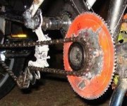
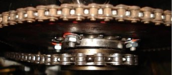
But basically you just bolt it on as you would have to the four-hole type. That's how I bolted on my four-hole 1/2" 110T to a 16T freewheel:
ChainwheelFreewheel.JPG
LeftRear.JPG
ChainlinesFromRear.JPG
View attachment 6

Though I would use 1/4"x20 bolts now, if I were to go back and do it again.

I'll look through the old pots and pans out in the shop tomorrow...great idea!

Sure, at 90v it wants to spin closer to 4675rpm, not 3600rpm. Losing about 1000rpm shouldn't be that bad though..the controller compensates pretty well. I wish I knew how the controller really works.
Depends on the type of controller. I don't know that particular one specifically. Which part did you need to know about? The limiting?

Obviously at really low speeds like 250rpm there's no oomph there, but from my limited testing, even at 1000rpm a 16t sprocket will chew wood pretty well despite running off a 350w inverter.
At very high RPM it's harder to slow it down. :) But when you are running the same ratios at a lower input speed from the same motor, you are putting less power into it, so it is naturally easier to stop it.

If you ran the same motor with different ratios of connecting drivetrain to get those different speeds, but the same power input at either speed, you would probably find that the lower speed would actually be harder to stop and would chew up wood even better. ;)

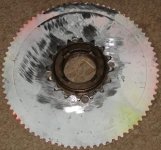
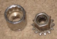
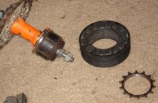
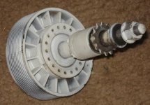
BTW, if it helps you at any point, this is what I used to get the reduction stages connected on mine, and add a freewheel into the motor input stage (before I ended up just bolting the big chainring to one).
ChainwheelSocket.JPG
PulleyFreewheelHubSprocketApart.JPG
View attachment 3
View attachment 2
MotorAndPulleyHubOnBikeRight.JPG


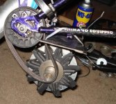
And this is an early version of that drivetrain, not yet all hooked up:
 

Attachments

  • treadmill motor freewheel  to 1-2inch chain adapter DSC02481.JPG
    treadmill motor freewheel to 1-2inch chain adapter DSC02481.JPG
    38.7 KB · Views: 3,752
amberwolf, nice pics. I'll probably do it like that since I've already got the 16t freewheel. If I can get a 48t sprocket on the wheel then I'm done...

The current frame incorporates the crank (no pedals/arms) of a mountain bike, flipped backwards so that the 48t sprocket is on the wrong side to drive the wheel. The motor's 16t sprocket drives the 48t sprocket on the crank. On the side opposite the 48t sprocket I have a 16t sprocket on the crank which then goes to the wheel. Since my wheel has a 16t sprocket on it there's no second gear reduction.

If I don't change the chain-line too much then a 48t sprocket on the wheel will give me a second 3:1.

It is only limited by the very low internal resistance. You can easily draw several hundred amps from one [...]

I think that's all I really needed to know. So I could run a 1kw inverter (for instance) off of a pair of high-discharge 12v, 20ah vrlas no problem...they just wouldn't shed 1kw for very long before dying or melting into goo. 1kw at 12v is like 82amps...sounds like jumper cable territory...

I'll probably limit the controller to the "3/4HP" setting anyway. According to the manual that means 90v and 7.6amps, or 684w. That should be more than enough.

Or bolt a "top hat" adapter to the sprocket

Didn't think about that. Good idea but I hope to avoid having to go there.

liveforphysics..
Running a brushed DC motor under-voltage = fail. The power decreases at the square of voltage, because current (torque) drops with speed.

90v is pretty close to 130v and technically the controller will run the motor at 180v if I want to over-volt. Literally just a flip of a switch.

If you want to get power from the motor, you need it to reach the RPM range at which it has power. This means gearing it to suit the power-band.

Exactly the issue I've been having since I had to stop working on the trailer. With the current gear ratio it's like my trailer has 6th through 12th gear...no first, no low-range at all.

With 350w max from the inverter the trailer still pushes itself and the bike (near 50lbs) up to about 4mph. This is with a single 3:1 reduction so 3600rpm at the motor means the wheel wants to spin at 1200rpm (71mph). At 4mph my wheel is only spinning around 80rpm so the motor is running around 240rpm.

It seems obvious to me that the only issue is the gear ratio and that the trailer will work once that's sorted.
edit; With another 3:1 reduction, 4mph will mean 720rpm at the motor instead of 240rpm.

You need to stack batteries to get the voltage you need. If it's a 130vdc motor, then you better stack 10x 12v batteries if you want to get any performance and efficiency. Inverters are not optimized for this.

Running 10 batteries in series isn't the only way to get high voltage. Inverters convert low voltage DC into high voltage AC and that's all they do...they're pretty well optimized for it. The controller I have is designed to convert high voltage AC into high voltage DC to run the motor....it's typically run off the grid but it's physically small enough that I'm sure they didn't intentionally design it to waste power or it would have heat problems.

We'll see.
 
Back
Top